Hitachi NJI-350B User Manual
Page 80
Chapter 5 Instruction Specifications
5-30
Item number
Basic instructions-23
Name
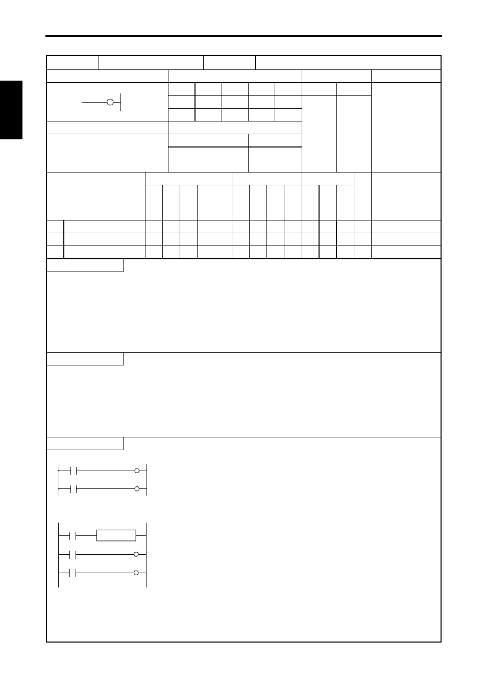
Single shot (SINGLE SHOT)
Ladder format
Condition code
Processing time (
µs)
Remark
R7F4
R7F3
R7F2
R7F1
R7F0
Average Maximum
DER
ERR
SD
V
C
z
z
z
z
z
Instruction format
Number of steps
1.4
Condition
Steps
OUT SS n t s
5
Bit
Word
Double word
Usable I/O
X
Y
R,
M
TD, SS,
WDT, MS,
TMR, CU,
RCU, CT WX WY
WR,
WM TC DX DY
DR,
DM
Co
n
sta
n
t
Other
n
Timer number
{ 0 to 255 (Decimal)
t
Time base
.01s, .1s, 1s
s
Set value
{
{
{
{ 1 to 65535 (Decimal)
Function
• Detects the leading edge of the startup condition, starts updating progress values, and turns on the coil.
• The coils turns off when the progress value is greater than or equal to the set value. If a leading edge is detected while the
progress value is less than the set value, the progress value is set to 0 and the counter is reset.
• The progress value is set in TC n and does not exceed 65535 (decimal).
• If the progress value is updated during RUN, the operation will be performed using the new progress value at that point.
• If an I/O is set for the set value, the set value can be changed during operation by changing the I/O value, since the set values
are updated during each scan.
Notes
• The .01 s time base can only be used for timer numbers 0 to 63 (64 points).
• The .1 s and 1s time bases can be used for all timer numbers (0 to 255).
• A maximum of 256 points can be used for the timers TD, SS, CU, CTU and CTD in total.
However, the same area as the counter is used. Timer number and counter number may not be overlapped.
• Since the startup condition of a single shot is edge detection, the condition for one scan cannot be detected during the first
scan after RUN starts.
Program example
X00001
SS11
LD
X00001
OUT
SS11 0.01S 12567
LD
SS11
OUT
R101
SS11
R101
0.01S 12567
• An example of a word I/O being used as the set value for the circuit shown above.
R7E3
X00001
SS11
0.01S WR0011
SS11
R101
WR0011=12567
LD
R7E3
[
WR0011=12567
]
LD
X00001
OUT
SS11 0.01S WR0011
LD
SS11
OUT
R101
SS n
t x s
O
U
T
S
S
n
t
s