Hitachi NJI-350B User Manual
Page 53
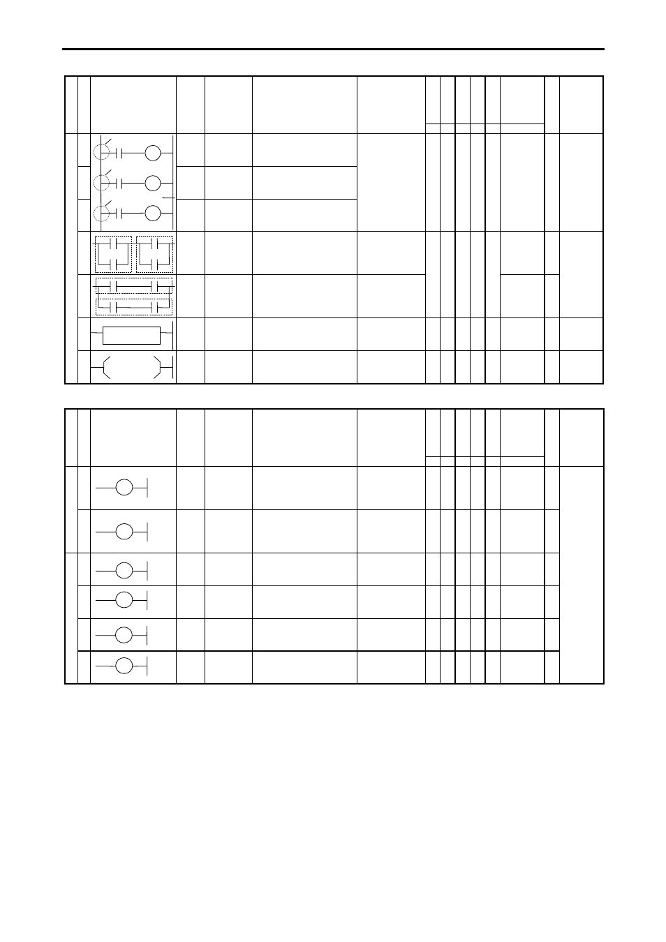
Chapter 5 Instruction Specifications
5-3
R7F
4
R7F
3
R7F
2
R7F
1
R7F
0
Process
time
(
µ s)
C
la
ssi
fica
tio
n
It
em
num
ber
Ladder symbol
In
str
ucti
on
sy
m
bol Instruction
name
Process descriptions
I/O types used
DER ERR SD
V
C
MICRO-EH
S
teps Remarks
15
MPS
MPS Operation
result push
Stores the previous
operation result.
None
z z z z z
—
0
16
MRD
MRD Operation
result read
Reads the stored operation
result and continues
operation.
17
MPP
MPP Operation
result pull
Reads the stored operation
result, continues operation
and clears the stored result.
Se
que
nce
ins
tr
uctio
ns
18
ANB Logical
block serial
connection
Indicates serial connection
between two logical blocks.
None
z z z z z
—
0
19
ORB Logical
block
parallel
connection
Indicates parallel
connection between two
logical blocks.
None
0.7
1
20
[ ]
Processing
box start
and end
Indicates start and end of a
process box.
None
z z z z z
0.6
3
21
( )
Relational
box start
and end
Indicates start and end of a
comparison box.
None
z z z z z
0.8
0
2.
Basic instructions (timer, counter)
R7F
4
R7F
3
R7F
2
R7F
1
R7F
0
Process
time
(
µ s)
C
la
ssi
fica
tio
n
It
em
num
ber
Ladder symbol
In
str
ucti
on
sy
m
bol Instruction
name
Process descriptions
I/O types used
DER ERR SD
V
C
MICRO-EH
S
teps Remarks
Ti
m
er 22
TD
OUT
TD
On delay
timer
Indicates an on delay timer
operation.
TD0 to TD255
When 0.01 s, it is
possible to use
until 0 to 63.
z z z z z
1.4
5 Number
overlap not
allowed
23
SS
OUT
SS
Single shot Indicates a single shot
operation.
SS0 to SS255
When 0.01 s, it is
possible to use 0
to 63.
z z z z z
1.4
5
24
CU
OUT
CU
Counter
Indicates a counter
operation.
CU0 to CU255
z z z z z
1.4
5
25
CTU
OUT
CTU
Up of
up/down
counter
Indicates an up operation of
up-down counter.
CTU0 to
CTU255
z z z z z
1.4
5
Co
unte
r
26
CTD
OUT
CTD
Down of
up/down
counter
Indicates a down operation
of up-down counter.
CTD0 to
CTD255
z z z z z
1.4
3
27
CL
OUT
CL
Counter
clear
Indicates a clear operation
for CU, RCU, CTU, CTD
and WDT.
CL0 to CL255
z z z z z
0.9
1