Hitachi NJI-350B User Manual
Page 187
Chapter 5 Instruction Specifications
5-137
Item number
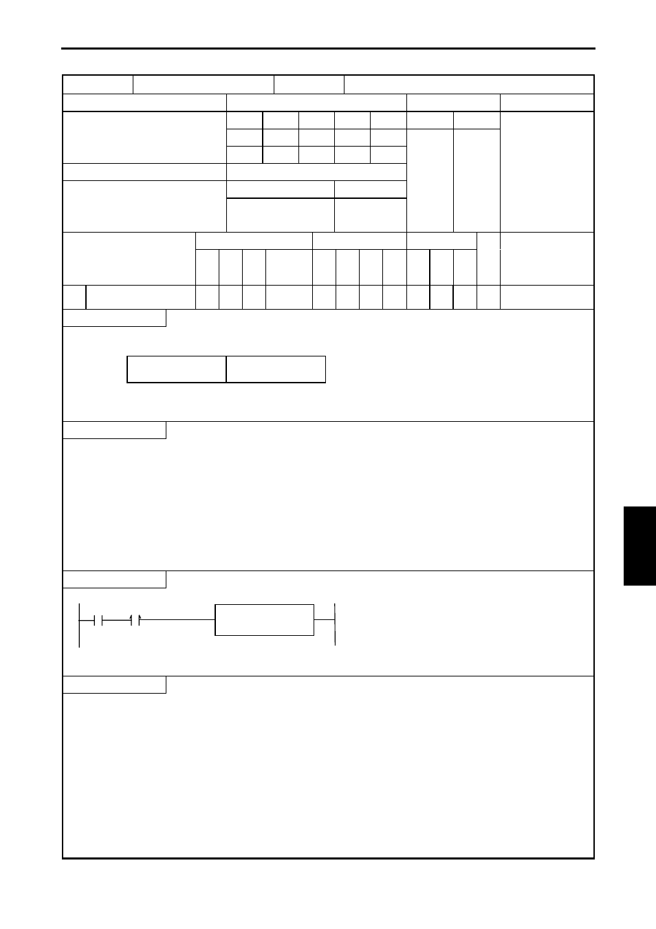
FUN instructions-12
Name
PWM operation control
Ladder format
Condition code
Processing time (
µs)
Remark
R7F4
R7F3
R7F2
R7F1
R7F0
Average Maximum
FUN 147 (s)
DER
ERR
SD
V
C
↕
z
z
z
z
Instruction format
Number of steps
135
Condition
Steps
FUN 147 (s)
—
3
Bit
Word
Double word
Usable I/O
X
Y
R,
M
TD, SS,
CU, CT
WX WY
WR,
WM TC DX DY
DR,
DM
C
o
nstant
Other
s
Argument (PWM output
number)
{
Function
PWM output number: H01 to H04
Operation instruction: H00 – Stop,
H01 - Start
• Starts/stops the PWM output of the specified PWM output number.
Notes
• If a value other than H01 to H04 is specified as the PWM output number, DER will be set to “1” and no processing will be
performed.
• If the external I/O corresponding to the PWM output number is set to a function other than PWM output, DER will be set to
“1” and no processing will be performed.
• If PWM output is activated with this instruction, the output control flag (R7FC to R7FF) corresponding to the specified
PWM output number will turn on and off.
• The PWM output operation does not stop, even when CPU operation is stopped.
• When the CPU is not operating, the PWM output continues/stops according to the setting of the special internal output
(output selection at R7DC stop).
Program example
R7
LD R7
AND DIF7
[
WR7 = H101
FUN 147 ( WR7 )
]
DIF7
WR7 = H0101
FUN 147 (WR7)
Program description
• Prior to starting a PWM output operation, various settings required for the PWM output operation are reflected in the
special internal outputs, and the PI/O function setting flag (R7F5) is turned on while the CPU is being stopped.
For details on the special internal output settings, see Chapter 8.
Starts the PWM output No. 1 (Y100) operation.
S
PWM output number
Operation instruction
15
8 7
0
FUN 147 (s
)