Hitachi NJI-350B User Manual
Page 167
Chapter 5 Instruction specifications
5-117
*1
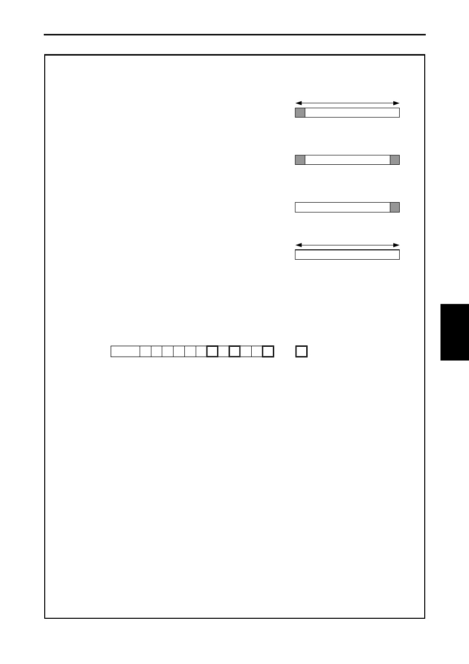
Received data is defined by either of following 4 ways depending on setting in [7] s+A to [9] s+C.
(a) Start code and data size
*2
s+A : Data length (Byte)
s+B : H80 (=Start code)
s+C : H0000
(b) Start and end code
*2
s+A : H0000
s+B : H80 (=Start code)
s+C : H80 (=End code)
(c) End code
s+A : H0000
s+B : H0000
s+C : H80 (=End code)
(d) Data length
s+A : Data length (Byte)
s+B:H0000
s+C:H0000
*2
In case of start code used, CPU can fail to receive due to buffer size full if data with wrong start code is sent.
(6) "t" parameter
: Set by user
[0]
[1]
[2]
[3]
[4]
[5]
[6]
[7]
[8]
[9]
[A]
[B]
t
t+B
[0] Execution bit:
Set "1" by user program to send data. This bit is reset after communication completed.
[1] Communication completed :
This bit is set "1" when communication completed without error, and reset at communication starting.
[2] Communication failed :
This bit is set "1" when communication fails, and reset at communication starting.
[3] Initialize :
Set "1" by user program to initialize TRNS 0 command. If this bit is on while communication, the communication
is forced to be stopped.
[4] Initialize completed :
This bit is set "1" when initializing completed without error. Initialize bit [3] is reset at this timing.
[5] Receive enabled :
Set "1" by user program if CPU needs to receive data after data sending. This bit is reset after communication
completed.
[6] Parity error flag :
This bit is set "1" when parity error detected.
[7] Framing error :
This bit is set "1" when framing error detected.
[8] Overrun error :
This bit is set "1" when overrun error detected.
TR
N
S
0
(
d, s, t)
Start code
Start code
End code
End code
Data length
Data length