Hitachi NJI-350B User Manual
Page 213
Chapter 8 High-speed counter, PWM / Pulse train output and Analogue I/O
8-4
8.1.4
Input/Output Setting (Mode 10)
Mode 10 had been added since Ver. 01.13. I/O assignment of mode 10 is very flexible as follows.
Parameter setting is compatible with existing mode 0 to 3 except for WRF071. Operation of FUN command (FUN 140 -
150) is same for all the mode 0 to 10.
Outline
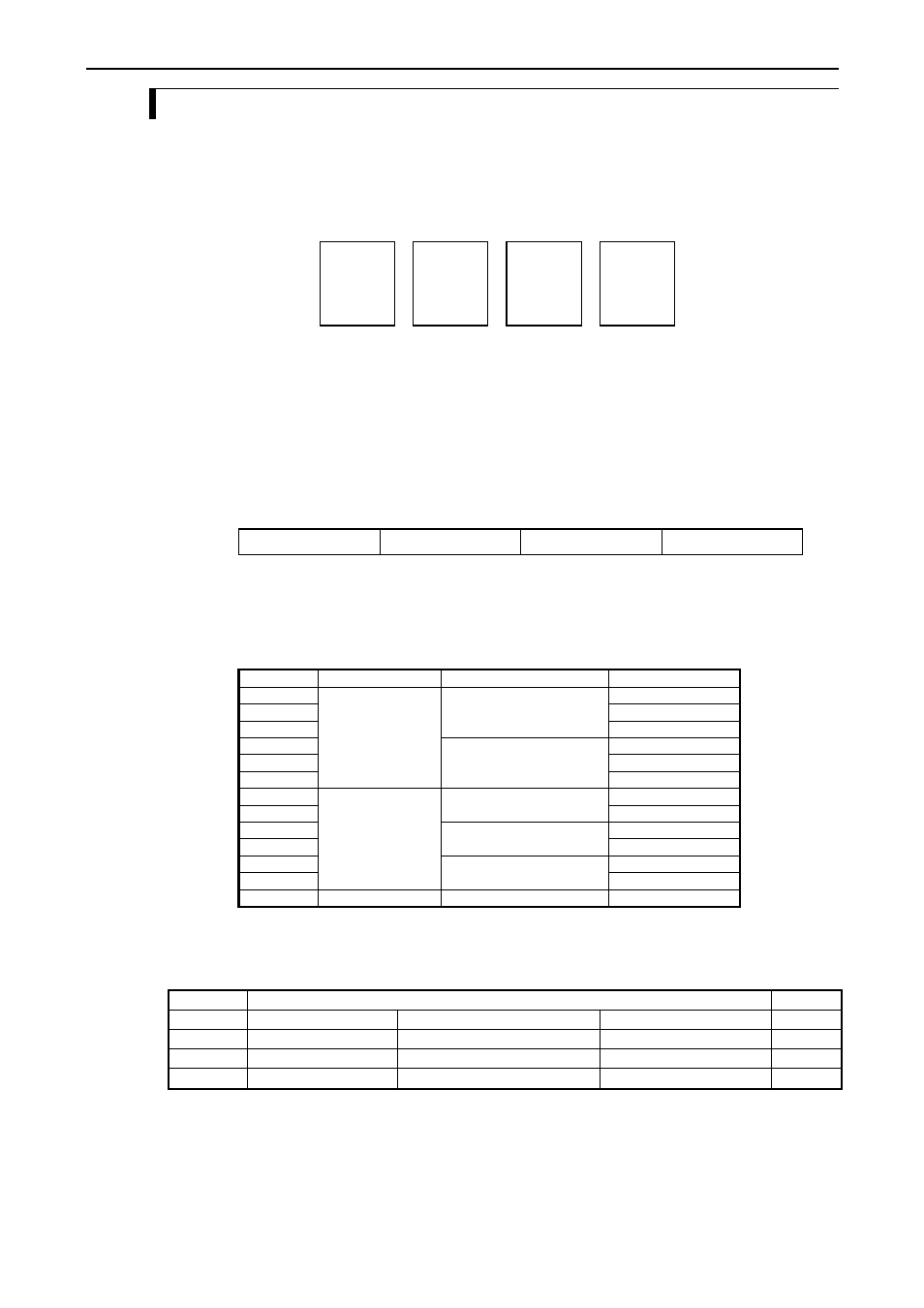
Input and output are configured in every group as below.
X0
X1
Y100
X2
X3
Y101
X4
X5
Y102
X6
X7
Y103
Group 1
Group 2
Group 3
Group 4
Fig. 8.4 Group of mode 10
Mode setting
Set "H10" to the special internal output WRF070.
In/output setting
Set parameter according to the following table to the special internal output WRF071.
Bit :
15
14
13
12
11
10
9
8
7
6
5
4
3
2
1
0
WRF071 :
Group 1
Group 2
Group 3
Group 4
Default :
0
0
0
0
0
0
0
0
0
0
0
0
0
0
0
0
Fig. 8.5 Bit table of WRF071
Select one of below combinations and set in WRF071 for every group.
Fig. 8.2 Parameter for in/output setting
Parameter
X0 / 2 / 4 / 6
X1 / 3 / 5 / 7
Y100/101/102/103
H 0
Standard input
Standard input
Standard output
H 1
PWM output
H 2
Pulse output
H 3
Interrupt input
Standard output
H 4
PWM output
H 5
Pulse output
H 6
Counter input
Standard input
Standard output
H 7
Counter output
H 8
Preload input
Standard output
H 9
Counter output
H A
Strobe input
Standard output
H B
Counter output
Others
Standard input
Standard input
Standard output
Since 10 points type does not have input X6 and X7, possible value for group 4 is 0 to 2.
Example
Group
Function
Value
1
X0 : Standard input
X1 : Standard input
Y100 : Pulse output 1
Î H2
2
X2 : Counter 2
X3 :Preload input 2
Y101 : Standard output
Î H8
3
X4 : Counter 3
X5 : Standard input
Y102 : Counter output 3
Î H7
4
X6 : Standard input
X7 : Interrupt input 4
Y103 : Standard output
Î H3
Î WRF071 = H2873