Hitachi NJI-350B User Manual
Page 52
Chapter 5 Instruction Specifications
5-2
The following lists the instructions.
1.
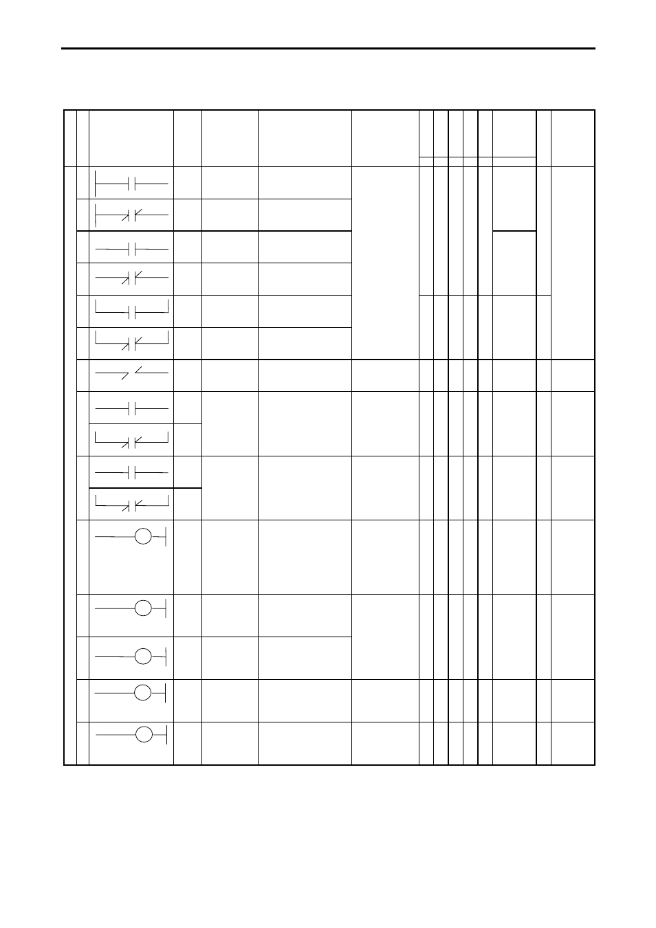
Basic instructions (sequence instructions)
R7F
4
R7F
3
R7F
2
R7F
1
R7F
0
Process
time
(
µs)
C
la
ssi
fica
tio
n
It
em
num
ber
Ladder symbol
In
str
ucti
on
sy
m
bol
Instruction
name
Process descriptions
I/O types used
DER ERR SD
V
C
MICRO-EH
S
teps Remarks
1
LD Logical
operation start
Indicates the
commencement of a-
contact operation.
z z z z z
0.9
1
2
LDI Logical
negation
operation start
Indicates the
commencement of b-
contact operation.
Se
que
nce
ins
tr
uctio
ns
3
AND Logical AND Indicates a-contact series
connection.
X, Y
R0 to R7BF
M0 to M3FFF
TD, SS, CU, CT
Timer: 0 to 255
Counter: 0 to 255
DIF0 to DIF511
DFN0 to
DFN511
0.8
4
ANI Logical
NAND
Indicates b-contact series
connection.
5
OR Logical OR
Indicates a-contact
parallel connection.
z z z z z
0.9
2
6
ORI Logical NOR Indicates b-contact
parallel connection.
7
NOT Logical NOT Reverses all operation
results up to that point.
None
z z z z z
0.8
2
8
DIF
AND
DIF
Leading edge
detection
Indicates detection of the
input rise.
DIF0 to DIF511
(Decimal)
z z z z z
1.0
3
4
Number
overlap not
allowed
DIF
OR
DIF
9
DFN
AND
DFN
Trailing edge
detection
Indicates detection of the
input fall.
DFN0 to
DFN511
(Decimal)
z z z z z
1.2
3
4
Number
overlap not
allowed
DFN
OR
DFN
10
OUT I/O output
Indicates an output coil. X, Y
R0 to R7BF
M0 to M3FFF
TD, SS, CU,
CTU, CTD, CL
Timer: 0 to 255
Counter: 0 to 255
z z z z z
1.0
1
11
SET
SET I/O set
Indicates set output.
X, Y
R0 to R7BF
M0 to M3FFF
z z z z z
0.9
1
12
RES
RES I/O reset
Indicates reset output.
13
MCS
MCS Set master
control
Indicates master control
set operation.
MCS0 to MCS49 z z z z z
0.7
3 Number
overlap
allowed
14
MCR
MCR Reset master
control
Indicates master control
reset operation.
MCR0 to
MCR49
z z z z z
0.7
2 Number
overlap
allowed