3 setting an input/output function, 3 input/output setting – Hitachi NJI-350B User Manual
Page 212
Chapter 8 High-speed counter, PWM / Pulse train output and Analogue I/O
8-3
8.1.3
Input/Output Setting
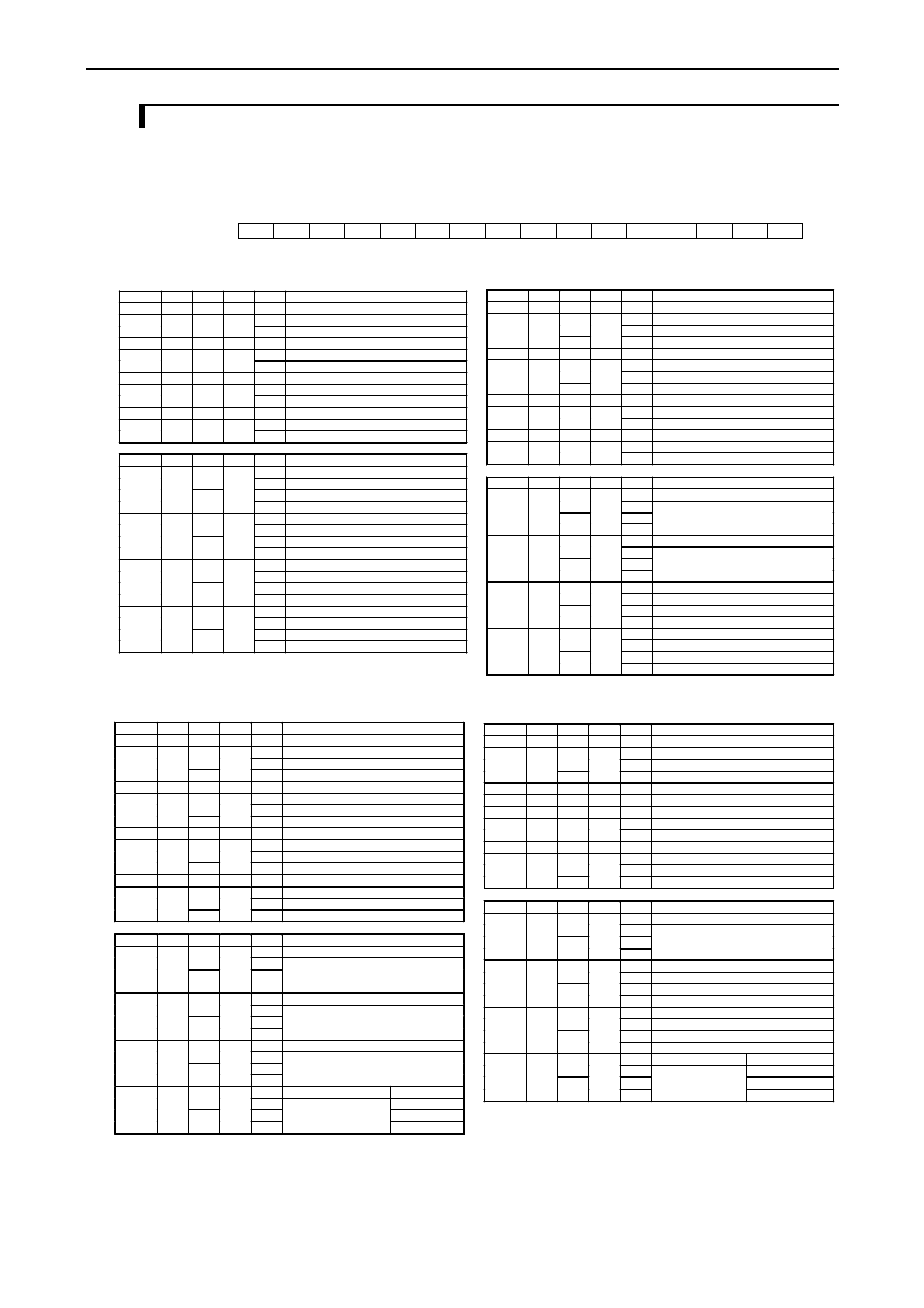
Configure each I/O setting in the special internal output (WRF071) and make it effective by setting R7F5 ON in CPU
STOP status. This information is normally reset at every power on, but this can be saved in the FLASH memory by
setting R7F5 ON after that.
Bit:
15
14
13
12
11
10
9
8
7
6
5
4
3
2
1
0
WRF071:
a
b
c
d
e
f
g
h
i
j
k
l
m
n
o
p
Initial value:
0
0
0
0
0
0
0
0
0
0
0
0
0
0
0
0
Figure 8.2 Special internal output for setting detailed function
Mode 0
Name
Bit
Value
Bit
Value
Function
X0
-
-
-
-
Standard input (Fixed)
0
Standard input
X1
a
0
b
1
Interrupt input
X2
-
-
-
-
Standard input (Fixed)
0
Standard input
X3
c
0
d
1
Interrupt input
X4
-
-
-
-
Standard input (Fixed)
0
Standard input
X5
e
0
f
1
Interrupt input
X6
-
-
-
-
Standard input (Fixed)
0
Standard input
X7
g
0
h
1
Interrupt input
Name
Bit
Value
Bit
Value
Function
0
Standard output
0
1
PWM output
0
Pulse output
Y100
i
1
j
1
-
0
Standard output
0
1
PWM output
0
Pulse output
Y101
k
1
l
1
-
0
Standard output
0
1
PWM output
0
Pulse output
Y102
m
1
n
1
-
0
Standard output
0
1
PWM output
0
Pulse output
Y103
o
1
p
1
-
Mode 1
Name
Bit
Value
Bit
Value
Function
X0
-
-
-
-
Counter input (Fixed)
0
Counter preload
0
1
Counter strobe
X1
a
1
b
0
Standard input *1
X2
-
-
-
-
Counter input (Fixed)
0
Counter preload
0
1
Counter strobe
X3
c
1
d
0
Standard input *1
X4
-
-
-
-
Standard input (Fixed)
0
Standard input
X5
e
0
f
1
Interrupt input
X6
-
-
-
-
Standard input (Fixed)
0
Standard input
X7
g
0
h
1
Interrupt input
Name
Bit
Value
Bit
Value
Function
0
Counter output
0
1
Standard output *1
0
Y100
i
1
j
1
0
Counter output
0
1
Standard output *1
0
Y101
k
1
l
1
0
Standard output
0
1
PWM output
0
Pulse output
Y102
m
1
n
1
-
0
Standard output
0
1
PWM output
0
Pulse output
Y103
o
1
p
1
-
*1 : Supported by software version.1.11 or newer.
Mode 2
Name
Bit
Value
Bit
Value
Function
X0
-
-
-
-
Counter input (Fixed)
0
Counter preload
0
1
Counter strobe
X1
a
1
b
0
Standard input *1
X2
-
-
-
-
Counter input (Fixed)
0
Counter preload
0
1
Counter strobe
X3
c
1
d
0
Standard input *1
X4
-
-
-
-
Counter input (Fixed)
0
Counter preload
0
1
Counter strobe
X5
e
1
f
0
Standard input *1
X6
-
-
-
-
Counter input (Fixed)
0
Counter preload
0
1
Counter strobe
X7
g
1
h
0
Standard input *1
Name
Bit
Value
Bit
Value
Function
0
Counter output
0
1
Standard output *1
0
Y100
i
1
j
1
0
Counter output
0
1
Standard output *1
0
Y101
k
1
l
1
0
Counter output
0
1
Standard output *1
0
Y102
m
1
n
1
0
Counter output
Std. output *2
0
1
Standard output *1
PWM output *2
0
Pulse output *2
Y103
o
1
p
1
*1 : Supported by software version 1.11 or newer.
*2 : Configuration for 10 point type.
Mode 3
Name
Bit
Value
Bit
Value
Function
X0
-
-
-
-
2 phase Counter 1A (Fixed)
0
Counter preload
0
1
Counter strobe
X1
a
1
b
0
Standard input *1
X2
-
-
-
-
2 phase counter 1B (Fixed)
X3
c
0
d
0
Counter input 1Z (Fixed)
X4
-
-
-
-
Standard input (Fixed)
0
Standard input
X5
e
0
f
1
Interrupt input
X6
-
-
-
-
Counter input (Fixed)
0
Counter preload
0
1
Counter strobe
X7
g
1
h
0
Standard input *1
Name
Bit
Value
Bit
Value
Function
0
Counter output
0
1
0
Y100
i
1
j
1
Standard output *1
0
Standard output
0
1
PWM output
0
Pulse output
Y101
k
1
l
1
-
0
Standard output
0
1
PWM output
0
Pulse output
Y102
m
1
n
1
-
0
Counter output
Standard output *2
0
1
PWM output *2
0
Pulse output *2
Y103
o
1
p
1
Standard output *1
-
*1 : Supported by software version 1.11 or newer.
*2 : Configuration of 10 point type.