Hitachi L100 User Manual
Page 45
Step-by-Step Basic Installation
In
v
e
rt
er M
o
unti
n
g
and I
n
st
all
a
ti
on
2–14
Wiring the Inverter Input to a Power Supply
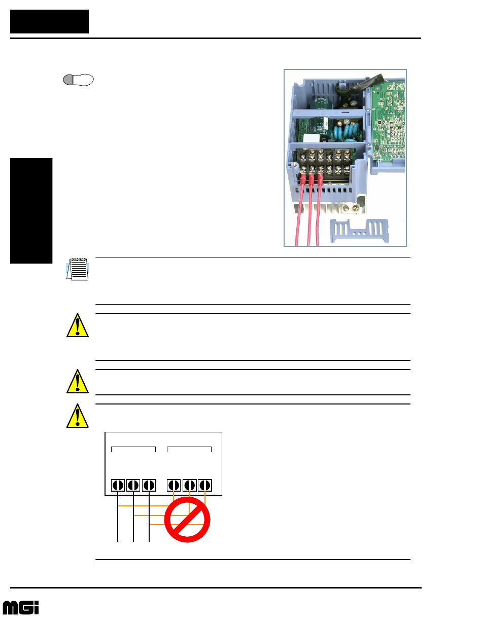
Step 6: In this step, you will connect wiring to
the input of the inverter. First, you must deter-
mine whether the inverter model you have
requires three-phase power only, or if it can
accept either single-phase or three-phase power.
All models have the same power connector
terminals labeled L1, L2, and L3/N. So, you
must refer to the specifications label (on the
side of the inverter) for the acceptable power
source types! For inverters which can accept
single-phase power and are connected that
way, terminal L2 will remain unconnected.
The wiring example to the right shows an L100
inverter wired for 3-phase input. Note the use of
spade lug connectors for a secure connection.
NOTE: An inverter powered by a portable power generator may receive a distorted
power waveform, overheating the generator. In general, the generator capacity should be
five times that of the inverter (kVA) in a PWM (pulse-width modulated) control system,
or six times greater in a PAM (pulse-amplitude modulated) control system.
CAUTION: Be sure that the input voltage matches the inverter specifications:
• Single/Three phase 200 to 240 V 50/60 Hz (up to 2.2kW)
• Three phase 200 to 230V 50/60Hz (above 2.2kW)
• Three phase 380 to 460 V 50/60Hz
CAUTION: Be sure not to input a single phase to a three-phase-only type inverter.
Otherwise, there is the danger of fire.
CAUTION: Be sure not to connect an AC power supply to the output terminals. Other-
wise, there is the danger of injury and/or fire.
6
Power Input
Power Output
L1 L2 L3
T1 T2 T3
U
V
W
(L)
(N)
NOTE:
L, N:
L1, L2, L3:
Single-phase 200 to 240V 50/60 Hz
Three-phase 200 to 230V 50/60 Hz
Three-phase 380 to 460V 50/60 Hz
Technologies Inc.
Toll Free: voice: 1-877-539-2542 fax: 1-800-539-2542 www.mgitech.com