Troub le shoot in g and maint enance – Hitachi L100 User Manual
Page 137
Maintenance and Inspection
T
roub
le
shoot
in
g
and Maint
enance
6–12
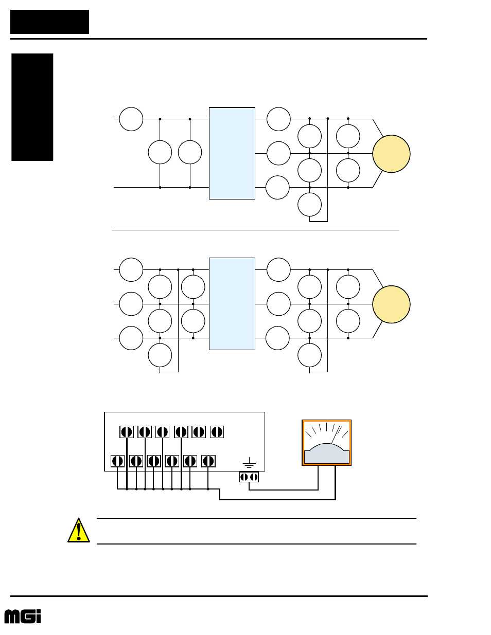
The figures below show measurement locations for voltage, current, and power measure-
ments listed in the table on the previous page. The voltage to be measured is the funda-
mental wave effective voltage. The power to be measured is the total effective power.
Conduct the insulation resistance test by short circuiting the terminals as shown below.
CAUTION: Never test the withstand voltage (HIPOT) on the inverter. The inverter has a
surge protector between the main circuit terminals above and the chassis ground.
E
1
W
1
I
1
I
1
I
1
I
1
E
U-V
E
U-V
E
U-V
W
01
W
02
INVERTER
MOTOR
L
1
N
U/T1
V/T2
W/T3
L
1
N
Single-phase measurement diagram
E
1
I
1
I
1
I
1
I
1
E
U-V
E
U-V
E
U-V
W
01
W
02
INVERTER
MOTOR
L1
N
U/T1
V/T2
W/T3
L1
N
Three-phase measurement diagram
W
01
W
02
E
1
E
1
I
2
I
3
L2
U
V
W
Meg ohm meter
L1
L2
L3
U
V
W
RB +1
+
–
Technologies Inc.
Toll Free: voice: 1-877-539-2542 fax: 1-800-539-2542 www.mgitech.com
- C 7D (92 pages)
- DV18DMR (96 pages)
- DH 40FA (34 pages)
- SERIES D (28 pages)
- 231580 (34 pages)
- 206700 (24 pages)
- WH14DM OM (76 pages)
- DS 12DVF2 (4 pages)
- SJ-PB(T) (35 pages)
- NT 65M (4 pages)
- DH 40MRY (62 pages)
- RTX 900 (34 pages)
- DH 24DV (88 pages)
- FDS 9DVA (60 pages)
- L100 300 (16 pages)
- G13SE2 (52 pages)
- N 5008AC (42 pages)
- L300P (264 pages)
- DH 38YE (64 pages)
- CONVENTION 14 (305 pages)
- DS 14DVB (4 pages)
- H 45MR (52 pages)
- WH9DM2 (108 pages)
- B 16RM (64 pages)
- DH 24PD (28 pages)
- L300P Series (76 pages)
- W 8VB (52 pages)
- SJ2-CO (35 pages)
- CR 10DL (56 pages)
- DS18DVB2 (30 pages)
- WR 9DM (98 pages)
- CR 18DV (80 pages)
- 24PD (58 pages)
- SJ100 (214 pages)
- G 18MR (52 pages)
- 308640 (28 pages)
- DH 45MR (68 pages)
- NR90AA (48 pages)
- 232624 (24 pages)
- SJ700-2 (284 pages)
- 288466 (14 pages)
- SJ-DG (20 pages)
- C6DD (22 pages)
- VARIABLE SPEED DV 18DV (68 pages)