Oper ati ons and m oni to ri ng – Hitachi L100 User Manual
Page 117
Analog and Digital Monitor Output
Oper
ati
ons
and M
oni
to
ri
ng
4–26
Current Monitor, PWM Signal – (C23 = 01) – The [FM] output duty cycle varies with
the inverter output current to the motor. The signal period T is fixed at 4 ms, and the
amplitude is fixed at 10 VDC. The signal on [FM] reaches full scale when the inverter
output current reaches 200% of the rated inverter current. You can scale the duty cycle
by a scale factor setting with parameter B81. The accuracy of the current reading is given
by the equation:
NOTE: The monitor display accuracy (normally
±
20%, depending on the connected
motor’s characteristics) can be improved by the adjustment of parameter B32. If precise
current measurement is necessary, use the moving-coil type ammeter between the
inverter and the motor.
TIP: When using the analog meter for monitoring, adjust the meter so it has a zero
reading when the [FM] output is zero. Then use scale factor B81 to adjust the [FM]
output so the maximum frequency in the inverter corresponds to a full-scale reading on
the meter.
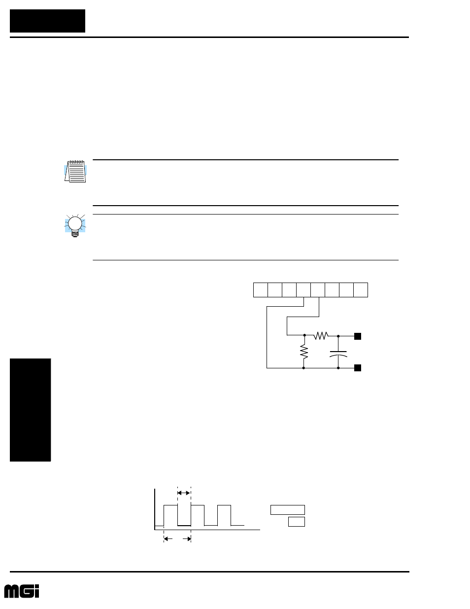
PWM Smoothing Circuit – You may need
to smooth the PWM signal, converting it to a
relatively stable DC analog voltage which
represents the [FM] output value. To do this,
use the circuit shown to the right. Note the
output impedance of the circuit is at least
82k Ohms, so the monitoring device needs
an input impedance of 1 Meg. Ohms or
greater. Otherwise, the impedance of the
smoothing circuit will cause a non-linearity
in the reading.
Frequency Monitor, FM Signal – (C23 = 02) – The [FM] output frequency varies with
the inverter output frequency. The maximum frequency of [FM] is 3.6 kHz, or 10 times
the inverter maximum frequency. The signal on [FM] reaches the maximum frequency
when the inverter outputs the maximum frequency. You can scale its relationship to the
inverter output with the scale factor setting with parameter B86.
Imc
Im
–
Ir
----------------------
100
×
20%
±
≤
Im = Inverter output current (measured)
Imc = Monitor display current
Ir = Inverter rated current
11
12
CM2
FM
O
L
OI
H
+
–
+
–
33k
Ω
82k
Ω
+
1
µ
F
Volts
See I/O specs on page 4–5.
C23 = 02
T
1
Output value
-------------------------------
=
Inverter output frequency
0 V
time
[FM]
10V
T
50% fixed duty cycle
Frequency modulation (digital)
B86 Freq. scale factor
Technologies Inc.
Toll Free: voice: 1-877-539-2542 fax: 1-800-539-2542 www.mgitech.com