2 carriage unit removal, Figure 3-10. front frame removal, G9 3-11. carriage unit removal – Epson 4003353 User Manual
Page 73
Disassembly and
Stylus Color service
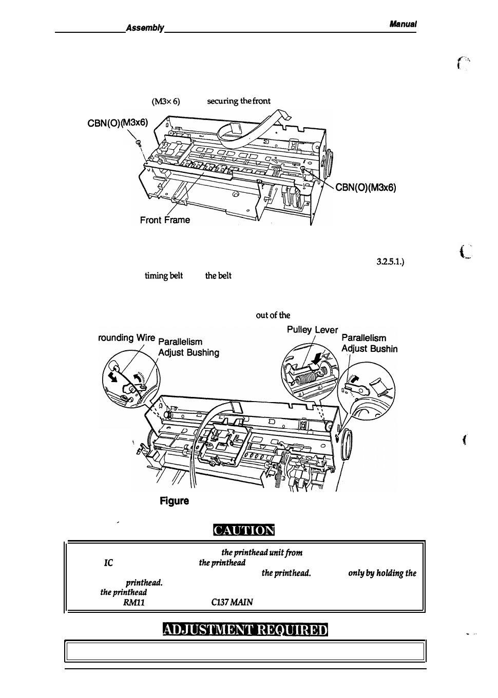
3.2.5.2 Carriage Unit Removal
1. Remove the printer mechanism. (See section 3.2.4.)
2. Move the carriage to the left side of the printer while pressing the hook that fixes the carriage
to the home position.
3. Remove the 2 CBN (0)
screws
frame toboth side frames.
Figure 3-10. Front Frame Removal
4. Remove thecartridgeholder with inkcartridge from the carriage unit. (See section
5. Release the carnage
from
pulley while pressing the pulley lever.
6. Remove thegroundingwire fromtheside frame (L).
7. Remove the 2 parallelism adjust bushings frombothside frames.
8. Lift the carriage unitwiththe carriage guide shaft
printer mechanism.
G
9
3-11. Carriage Unit Removal
■
Take a proper measurement to protect
static electricity, since the
driver
is directly attached to
unit.
■
Never touch the metallic nozzle surface cover of
Handle it
edges of the
■
When
or the printer mechanism is replaced, the block resistor must be replaced
at location
and RM12 on the
Board.
■
Platen gap adjustment (See Chapter 4.)
●
I
3-10
Rev. A