Epson 4003353 User Manual
Page 27
Stylus Color Service Manual
Product Description
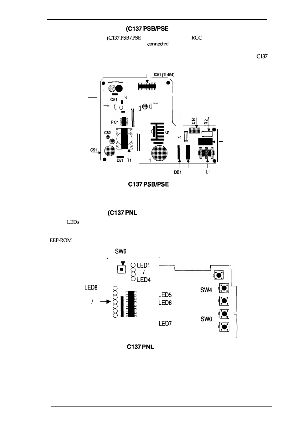
1.5.2 Power Supply Board
Board)
The
Power Supply Board
Board) consists of an
switching regulator circuit.
This board is equipped with a power switch
to the secondary circuit. Thus, if the printer
is turned off, it can continue to operate in order to eject the paper and perform the head capping
operation. The power on/off signal is always monitored by the E05A96 gate array on the
MAIN Board,
and the logic system recognizes the power switch status.
CN2 ,
n
I
. .
I
cl
C3
cl
Figure 1-10.
Component Layout
1.5.3 Control Panel
Board)
The 14
on this board indicate the error status (there is no buzzer system); by using the
6 switches in combination with one another, the printer can operate in each protect operation (color
or black cleaning, cartridge exchanging self-test, default setting value exchanging, reset, and
clear operation).
LED14
❑
0
0
0
●
0
/
n
Figure 1-11.
Board Component Layout
Rev.
A
1-19
- Stylus Pro 7800 (11 pages)
- Stylus Pro 4000 (49 pages)
- Stylus Photo R300 (2 pages)
- Stylus Pro 7000 (147 pages)
- AcuLaser C3000 (316 pages)
- Stylus Pro 7900 (24 pages)
- Stylus Pro 4450 (21 pages)
- 1000 (272 pages)
- T034120 (4 pages)
- T580300 (4 pages)
- 300 (91 pages)
- B 510DN (190 pages)
- B 510DN (218 pages)
- Stylus NX510 (8 pages)
- Stylus Photo RX580 (95 pages)
- T549300 (4 pages)
- B 500DN (168 pages)
- AculaserCX11NF (5 pages)
- 480SXU (24 pages)
- 4500 (317 pages)
- STYLUS RX500 (99 pages)
- 2100 (13 pages)
- Stylus NX215 (2 pages)
- T098320 (4 pages)
- T041020 (4 pages)
- R210 (8 pages)
- All-In-One Stylus Photo RX600 (164 pages)
- 777I (53 pages)
- T033120 (4 pages)
- Stylus CX7000F (8 pages)
- 60 (113 pages)
- T034220 (4 pages)
- WorkForce 40 Series (36 pages)
- T054220 (4 pages)
- Stylus CX3200 (11 pages)
- Stylus CX7800 (18 pages)
- T060220 (4 pages)
- 2500 (180 pages)
- AcuLaser CX11N (32 pages)
- AcuLaser CX11N (4 pages)
- 2000P (16 pages)
- T606600 (4 pages)
- Stylus CX6000 (18 pages)
- FS-4000DN (2 pages)
- MSDS T544700 (4 pages)