Epson 4003353 User Manual
Page 71
D i s a s s e m b l e
Stylus Color Service Manual
3.2.5 Printer Mechanism Disassembly
The procedures described in this section explain how to remove the components within the printer
mechanism.
3.2.5.1
Unit Removal
1. Remove the printer mechanism. (See section 3.2.4.)
2. Move the carnage to the middle of the printer while pressing the hook that fixes the carriage
unit to the home position.
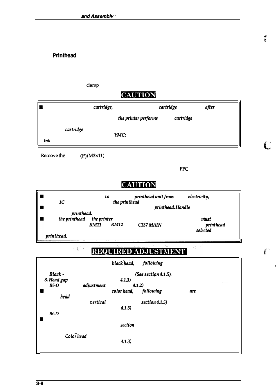
3. Pull the ink cartridge
toward you and remove the ink cartridge.
When removing the ink
always install a new
immediately
removing
the old one.
■
When the ink cartridge is replaced,
the ink
replacement
operation automatically.
Exclusive
is as follows; Monochrome: 1020626
1020627
■
cartridges should never be kept longer than 6 months.
4.
4 CBB
screws securing the ink cartridge holder to the carriage base,
and then lift the ink cartridge holder out of the carriage base.
5. Pull the black or color head toward you and disconnect the head
cable on the head driver
board (nozzle selector). Then remove the black or color head.
1
Take a proper measurement protect the
static
since the
driver
is directly attached to
unit.
Never touch the metallic nozzle surface cover of the
it only by holding the
edges of the
When
or
mechanism is replaced, the block resistor
be
replaced at location
and
on the
Board. (Every spare
or
spare printer mechanism comes with a block resistor that is specifically
for each
■
When removing or changing the
the
adjustments are needed.
1. Black head angle adjustment (See section 4.1.4)
2.
Color head vertical adjustment
adjustment (See section
4.
alignment
(See section
When removing or changing the
the
adjustments
needed.
L
Color
angle adjustment (See
section
4.1.6).
2. Black - Color head
adjustment (See
3. Head gap adjustment (See section
4.
alignment adjustment (See section 4.1.2)
When removing or changing both heads, the following adjustments are needed.
1. Color head angle adjustment (See
4.1.6)
2. Black head angle adjustment (See section 4.1.4)
3. Black -
vertical adjustment (See section 4.1.5.)
4. Head gap adjustment (See section
5. Bi-D alignment adjustment (See section 4.1.2)
Rev. A