Epson 4003353 User Manual
Page 46
Principles
Sty/us
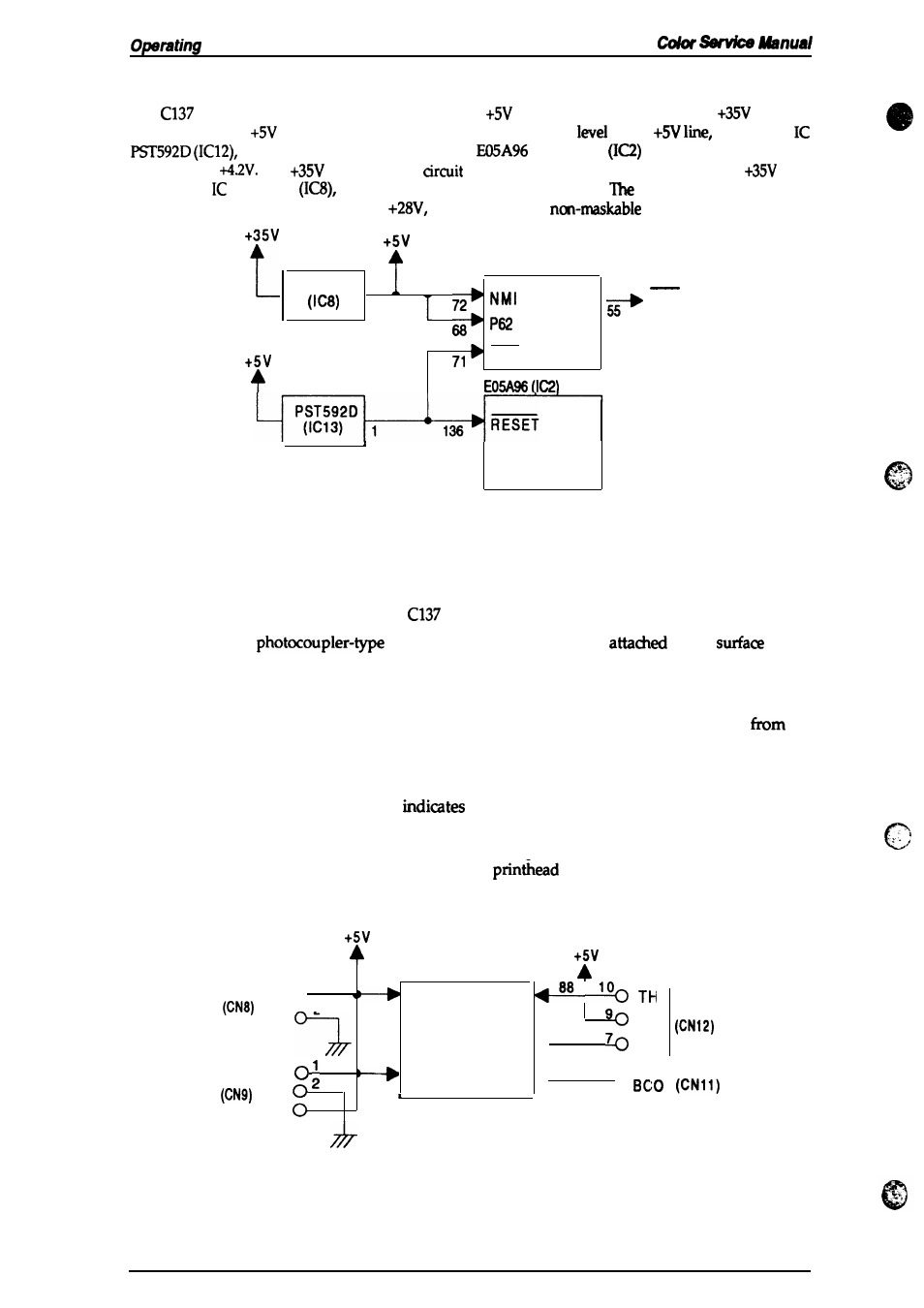
2.3.2.1 Reset Circuits
The
MAIN board
contains
2 reset circuits: the
monitor reset circuit and the
monitor
reset circuit. The
monitor reset circuit monitors the voltage
of the
using reset
and outputs a reset signal to the
gate array
when the voltage level
drops below
The
monitor reset
monitors the
voltage level of the
line,
using reset M51955B
and outputs a reset signal to the CPU.
reset signal is generated
when the voltage level drops
below
and this causes a
interrupt (NM).
CPU
(ICI)
M51 9556
.
‘6
PA8
RES
L
Figure 2-19. Reset
2.3.2.2 Sensor Circuits
RST
Type B
Circuit Block Diagram
‘. .,-
The following sensor circuits enable the
MAW board to monitor printer mechanism status:
HP sensor
A
HP (home position) sensor is
to the
of the
printer mechanism to detect the carriage home position. A LOW level from the
signal indicates that the carriage is m home position.
PE sensor A mechanical switch PE (paper end) sensor is built into the printer
mechanism to
determine whether there is paper in the printer or not.
A LOW
level
the
signal
indicates that no paper is loaded.
CO sensor
A micro switch is attached to the bottom of each ink cartridge holder in the carriage
unit. When the ink cartridge is installed, these switches are pressed and a LOW
level from the signal
that the ink cartridge is installed into the ink
cartridge holder.
Thermistor
A thermistor is attached to the color
printhead
driver board to monitor its
temperature. The
CPU changes the
drive signal’s pulse width (charge
pulse width) based on the temperature level.
CPU (lCl)
-
[
1
“
0
2
AN1
AN2
-
AN5
●
“
86
cco-
[
“
:
HP
ANO
AN4
4 “ 70
3
Figure 2“20.
I
Sensor Circuit Block Diagram
2-16
Rev. A