16 synchronization, Synchronization – ARRI ALEXA 35 Body & PL Mount Set (LBUS) User Manual
Page 78
Synchronization
78
16 Synchronization
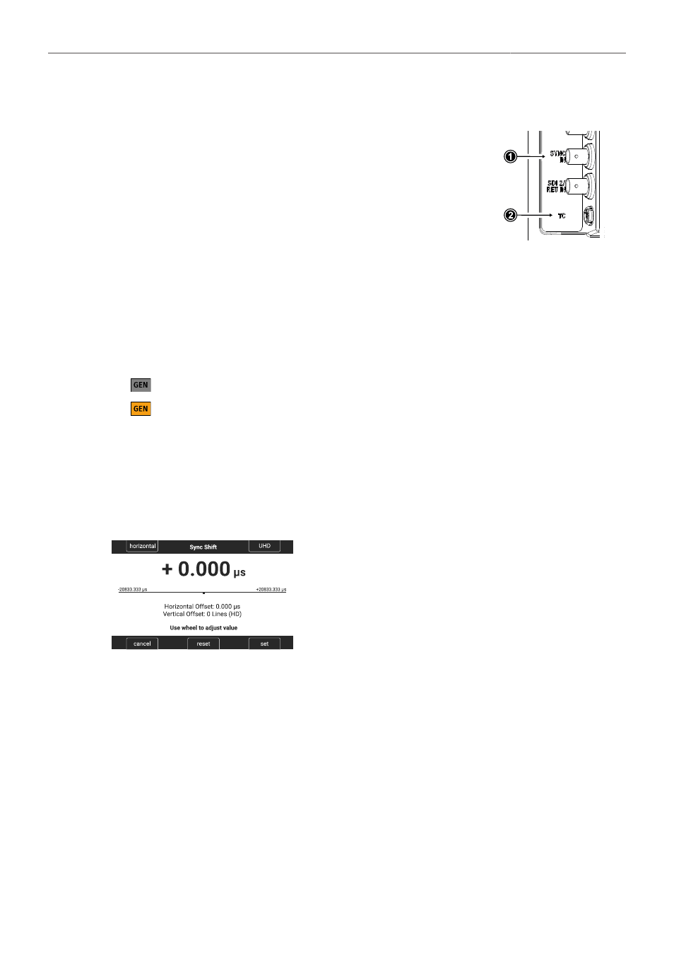
The camera's sensor and SDI outputs can be synchronized to either
a genlock signal (a tri-level HD signal or an analog black burst sig-
nal) present at the BNC SYNC IN connector (1) or a timecode signal
present at the 5-pin LEMO TC connector (2). The camera's sensor
needs to run at equal or double the frame rate of the reference signal
to establish synchronization.
► Select
MENU > System > Sensor > Genlock Sync
.
Following options are available:
Off
Sync In
Timecode
Synchronization is not enabled.
The camera will synchronize to a tri-level or black burst signal present at the SYNC IN connector.
The camera will synchronize to timecode present at the TC connector.
Active synchronization is indicated by the Genlock icon on the HOME screen and in the
Status Info. The icon turns orange when the camera cannot synchronize to the reference
signal or when no signal is present. See
MENU > Alerts
for detailed information.
Info:
Simultaneous use of the timecode mode
Jam-sync
and
Genlock Sync
is not supported.
Sync Shift
The Sync Shift setting can be used to apply an offset to the reference signal at the input. The minimum
step size is 52 ns and the maximum correction is +/- 20 ms, depending on the sensor frame rate.
► Select
MENU > System > Sensor > Sync Shift
.
► Use the upper left button to switch between horizontal
(minimum stepsize of 52ns) and vertical (entire lines)
shift.
► Use the upper right button to switch the vertical shift be-
tween HD and UHD lines.
► Use the clickwheel to adjust the shift.