ARRI ALEXA 35 Body & PL Mount Set (LBUS) User Manual
Page 34
Status Information and Overlays
34
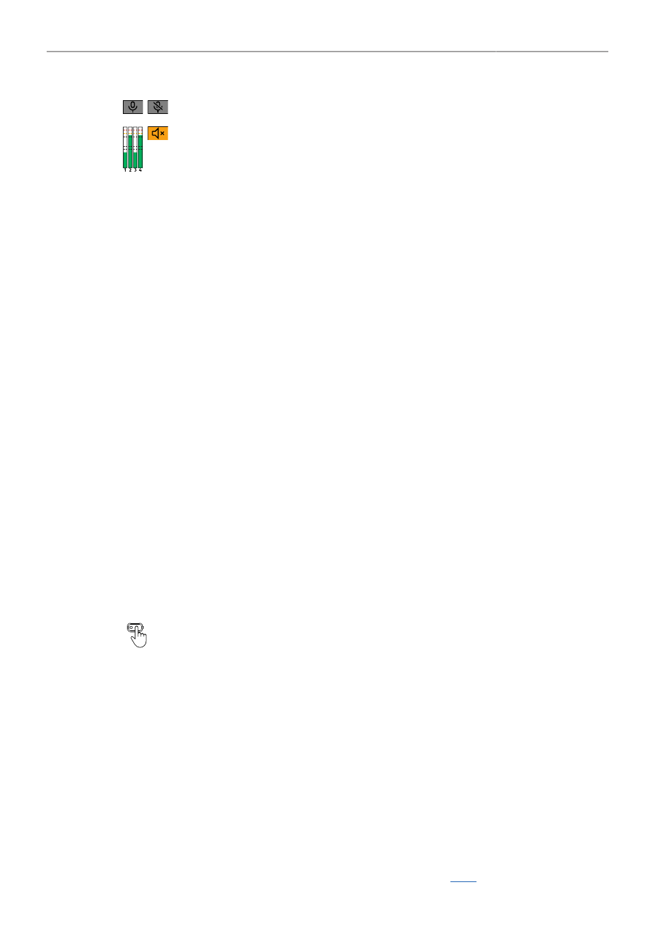
Internal microphone icons. Indicate that internal microphones are active/muted.
Audio meters. Indicate audio recording. Displays the current level of the audio channels.
If audio recording is not possible (e.g. sensor fps != project frame rate), an orange speaker icon is displayed
instead of the meters.
Black markers at signal levels -20, -18, -9 dBFS for reference test tone. Yellow marker at -5 dBFS and red
marker at -2 dBFS indicate a signal close to clipping. A red frame around the meter indicates a clipping at
the A/D stage.
Overlays
17
18
19
Center marker, marks the center of the image to help in framing.
Frame line (here: ARRI 1:2.39)
Electronic Horizon overlay. Can be set to display numeric roll and tilt values.
20
The Master Grips / OCU-1 Control overlay indicates which axis is controlled by connected Master Grips and OCU-1.
The overlay lights up white when there is control over the axis and gray when there is no control (e.g. no motor connected).
The overlay flashes orange briefly when control of the axis is lost (e.g. through override from a hand unit).
21
22
23
24
The focus distance overlay displays the current focus distance (if lens data is available).
Distance measure overlay, displays readings from distance measurement devices connected to the SERIAL connector.
DoF overlay displaying the calculated depth of field near focus distance (if lens data is available).
DoF overlay displaying the calculated depth of field far focus distance (if lens data is available).
Application of Status Info on Monitoring Outputs
► Select
MENU > Monitoring > VF > EVF Overlays > Status Info
to configure application of status
information for the EVF.
► Select
MENU > Monitoring > SDI > SDI 1 Processing > Overlays > Status Info
to configure
application of status information for the SDI 1 output.
► Select
MENU > Monitoring > SDI > SDI 2 Processing > Overlays > Status Info
to configure
application of status information for the SDI 2 output.
Following options are available:
Off
Overlay
Safe
Status information is not displayed.
Status information is displayed and overlaid on the captured image.
Status information is displayed around the captured image.
User Buttons
VF Status Info, SDI 1 Status Info
and
SDI 2 Status Info
support to quickly
set the Status Info on the respective output.
Configuration of Status Info Components
► Select
MENU > Monitoring > VF > EVF Overlays > Status Components
to configure the status
components for the EVF.
► Select
MENU > Monitoring > SDI > SDI 1 Processing > Overlays > Status Components
to configure
the status components for the SDI 1 output.
► Select
MENU > Monitoring > SDI > SDI 2 Processing > Overlays > Status Components
to configure
the status components for the SDI 2 output.
Following options are available:
Camera Index Letter
Displays the Camera Index Letter in the top right corner of the image (SDI only). Helps to
identify camera image output when shooting with multiple cameras.
Electronic Horizon
Displays a horizon overlay (19) representing the roll and tilt of the camera measured by
the camera's position sensor. This sensor can be