Status block – ProSoft Technology MVI69-101S User Manual
Page 82
MVI69-101S ♦ CompactLogix or MicroLogix Platform
Reference
IEC 60870-5-101 Slave Communication Module
Page 82 of 149
ProSoft Technology, Inc.
March 16, 2009
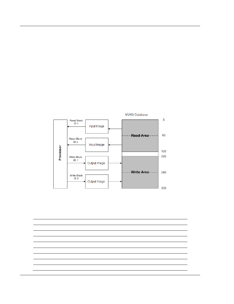
These areas are defined by the user when the configuration file is being edited.
The following parameters define the Read and Write data areas:
Read Register Start = 0
Read Register Count = 120
Write Register Start = 200
Write Register Count = 120
Each area is broken down into blocks of 60 words. Therefore, the Read Register
Count and Write Register Count parameters should be multiples of 60.
The Read Data Area will be transferred from the module to the CompactLogix or
MicroLogix processor. The Write Data Area will be transferred from the
CompactLogix or MicroLogix processor to the module.
The following example shows the resulting data flow:
5.2.3 Status
Block
The module periodically sends blocks 0 and -1 containing status information, as
described in the following table.
Offset Description
Length
0
Block Read ID
1
1
Block Write ID
1
2
Program Scan Counter
2
4 Product
Code
2
6 Product
Version
2
8 Operating
System
2
10 Run
Number
2
11
Backplane Read Count
1