1 program button (pattern generation), Figure 5-12. program lists window, 2 imported patterns – KEPCO KLP Series Developers Guide, Rev 3 User Manual
Page 75: 3 pattern generation window
KLP-DEV 041213
5-13
5.5.2.1
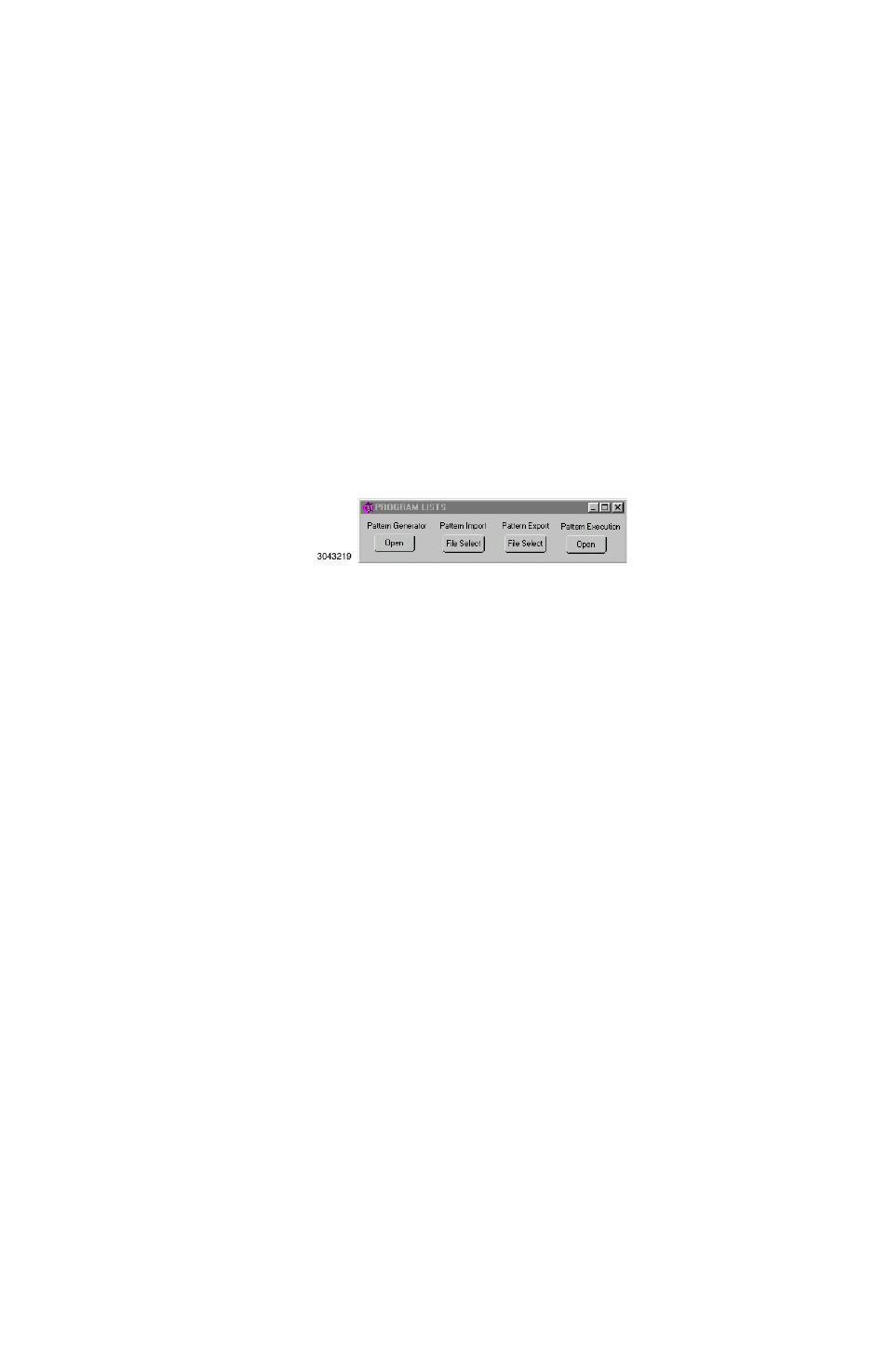
PROGRAM BUTTON (PATTERN GENERATION) (Standalone Configuration Only)
Running or generating a program (pattern) is accomplished by clicking the Program button on
the Main Panel, opening the Program Lists window (Figure 5-12). Programs can either be
defined point-by-point using the Pattern Generator Open button, or by using the Pattern
Import File Select button to import a file containing the program parameters. Once the program
is started, actual values of output current and voltage are displayed. If you exit the program
while the power supply is still on, the programmed settings in effect at that time are maintained
after exiting the program. Errors are discussed in PAR. 5.5.3.
The Pattern Generator Open button opens the Pattern Generation Window (see PAR. 5.5.2.3);
the Pattern Execution Open button opens the Pattern Execution window (see PAR. 5.5.2.8).
FIGURE 5-12. PROGRAM LISTS WINDOW
5.5.2.2
IMPORTED PATTERNS
Patterns can be imported in comma-delineated text format using the Pattern Import File Select
button (Figure 5-12). The format, showing a single data point, is illustrated in Figure 5-13 and
defined as follows:
The first line is a header, that defines columns (separated by commas) with a corresponding
parameter. The column with a “C” or “c” is defined as Current, “V” or “v” is defined as voltage,
“D” or “d” is defined as Dwell Time, and “Y” or “y“ is defined as Relay followed by (CR,LF). The
second line defines the first data point, with data separated by commas (in the same order as
defined by the header), followed by (CR,LF). Additional data lines define additional data points.
The EOF defines the end of the pattern. A pattern produced using the Pattern Generation win-
dow (Figure 5-14) can be saved in this format using the Pattern Export File Select button.
FIGURE 5-13. FORMAT FOR TYPICAL COMMA-DELINEATED PATTERN GENERATION FILE
5.5.2.3
PATTERN GENERATION WINDOW
The Pattern Generation window (Figure 5-14) allows a user-specified program of up to 250
points to be generated. This method of generating complex patterns, allows rigorous testing of a
UUT (Unit Under Test), within the boundaries determined by the virtual model and the load con-
ditions.
The GENERATED POINTS window shows the number of points currently included in the list for
each of the four parameters, CURRENT, VOLTAGE, DWELL and RELAY. The CLEAR LISTS
button clears all points in the list (individual points can be edited, but not deleted once they have
been added).
Current,Voltage,Dwell,Relay(cr,lf)
1.0123E+02,3.600E+02,1.0E-02,0(cr,lf)
(eof)