Section 2 - communication, 1 introduction, Figure 2-1. klp communication, block diagram – KEPCO KLP Series Developers Guide, Rev 3 User Manual
Page 19: 2 front panel (local) control, Front panel (local) control -1, Klp communication, block diagram -1
KLP-DEV 041213
2-1
SECTION 2 - COMMUNICATION
2.1
INTRODUCTION
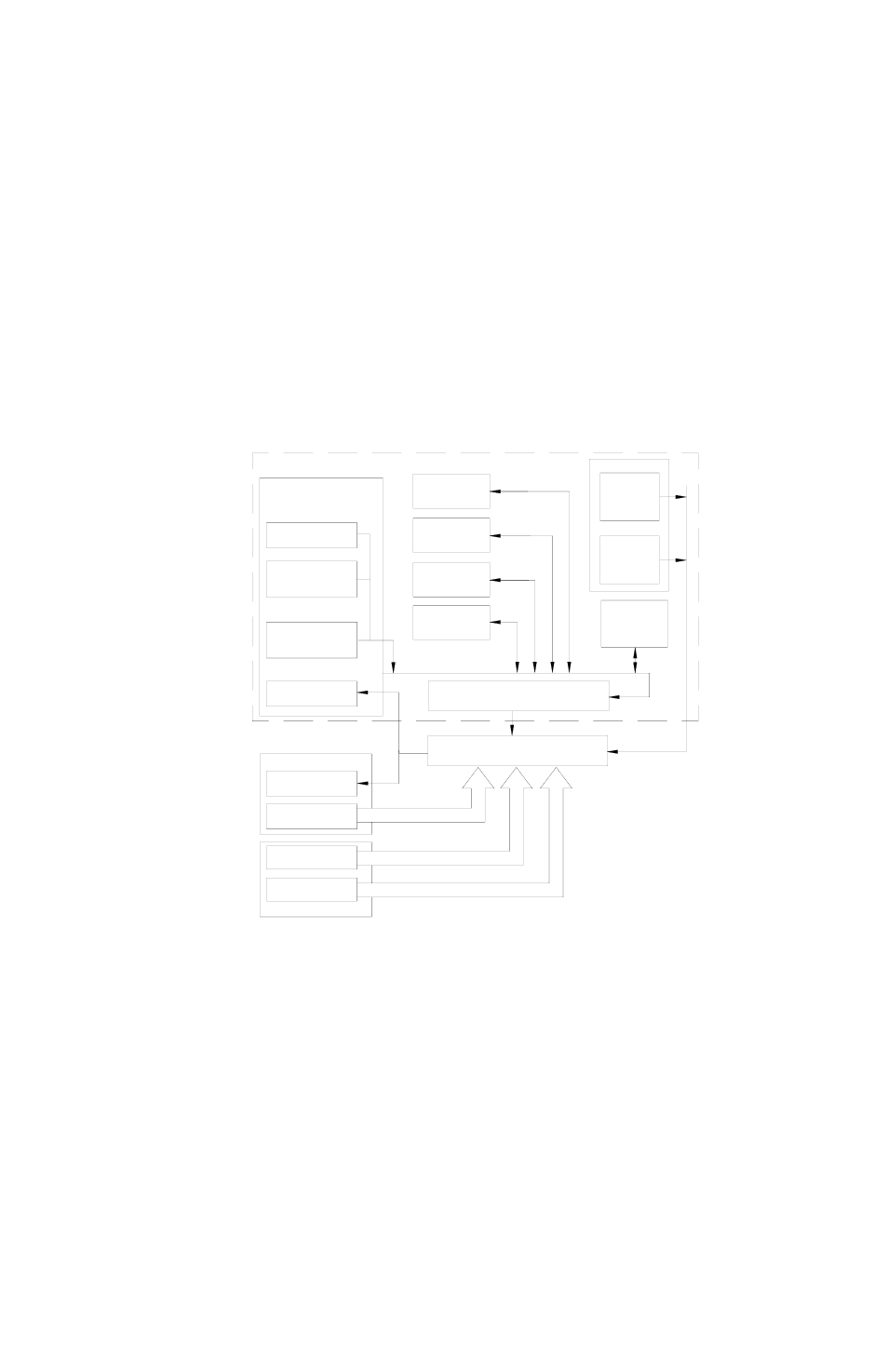
Figure 2-1 shows all paths used to communicate with the KLP. These include local control from
the front panel, GPIB, LAN (Ethernet) for E-Series models only, and RS 232 for standard mod-
els only.
FIGURE 2-1. KLP COMMUNICATION, BLOCK DIAGRAM
2.2
FRONT PANEL (LOCAL) CONTROL
Front panel control is the default upon power up (see the KLP User Manual). The unit automati-
cally enters remote mode upon receipt of a remote command. The front panel can be locked
and unlocked in all environments as shown in Table 2-1.
HOME PAGE
(UNIT DESCRIPTION)
LAN
CONFIGURATION
PAGE
OPERATE
INSTRUMENT
PAGE
WEB PORT 80
(8 CONNECTIONS)
STATUS
DISPLAY
FRONT PANEL
SUNRPC
PORT 111
UDP BROADCAST
SUNRPC
PORT 111
TCP/IP
UDP LXI
TRIGGER
PORT 5044
TCP/IP
TRIGGER
PORT 5044
TELNET
PORT 5024
2
CONNECTIONS
SCPI RAW
PORT 5025
2 CONNECTIONS
VXI-11
PORT 1024
4 CONNECTIONS
LAN PORT
LOCKING
INSTRUMENT
FUNCTIONS
CLASS A/B
STATUS
LOCAL CONTROL
SCPI, 488.2 LOCKING
GPIB
CONNECTION
3043146
LAN (ETHERNET) **
RS 232
CONNECTION *
REAR PANEL
* STANDARD MODELS ONLY
** E SERIES MODELS ONLY