1 monitor output voltage or current, 2 monitor unit status, 6 digital remote mode programming – KEPCO KLN 750W Series, Firmware Version 1.60 to 1.6x User Manual
Page 60: Monitor output voltage or current -24, Monitor unit status -24, Digital remote mode programming -24, Programming control port status monitoring -24, E 3-4)
3-24
KLN 750W 032614
3.5.6.1
MONITOR OUTPUT VOLTAGE OR CURRENT
CAUTION: DO NOT ALLOW SHORT BETWEEN PROGRAMMING CONTROL PORT PINS
20 (A MONITOR), 22 (V MONITOR) OR 24 (ANALOG COMMON) TO AVOID
DAMAGE TO THE UNIT.
Voltage: The analog voltage between 0 to +10V d-c at pin 20, referenced to pin 24, represents 0
to the rated voltage of the unit. Accurate within 5% of Voltage display reading. Output resis-
tance: approximately 100 Ohms, maximum output current: approximately 10mA.
Current: The analog voltage between 0 to +10V d-c at pin 22, referenced to pin 24, represents 0
to the rated current of the unit. Accurate within 5% of Current display reading. Output resis-
tance: approximately 100 Ohms, maximum output current: approximately 10mA.
3.5.6.2
MONITOR UNIT STATUS
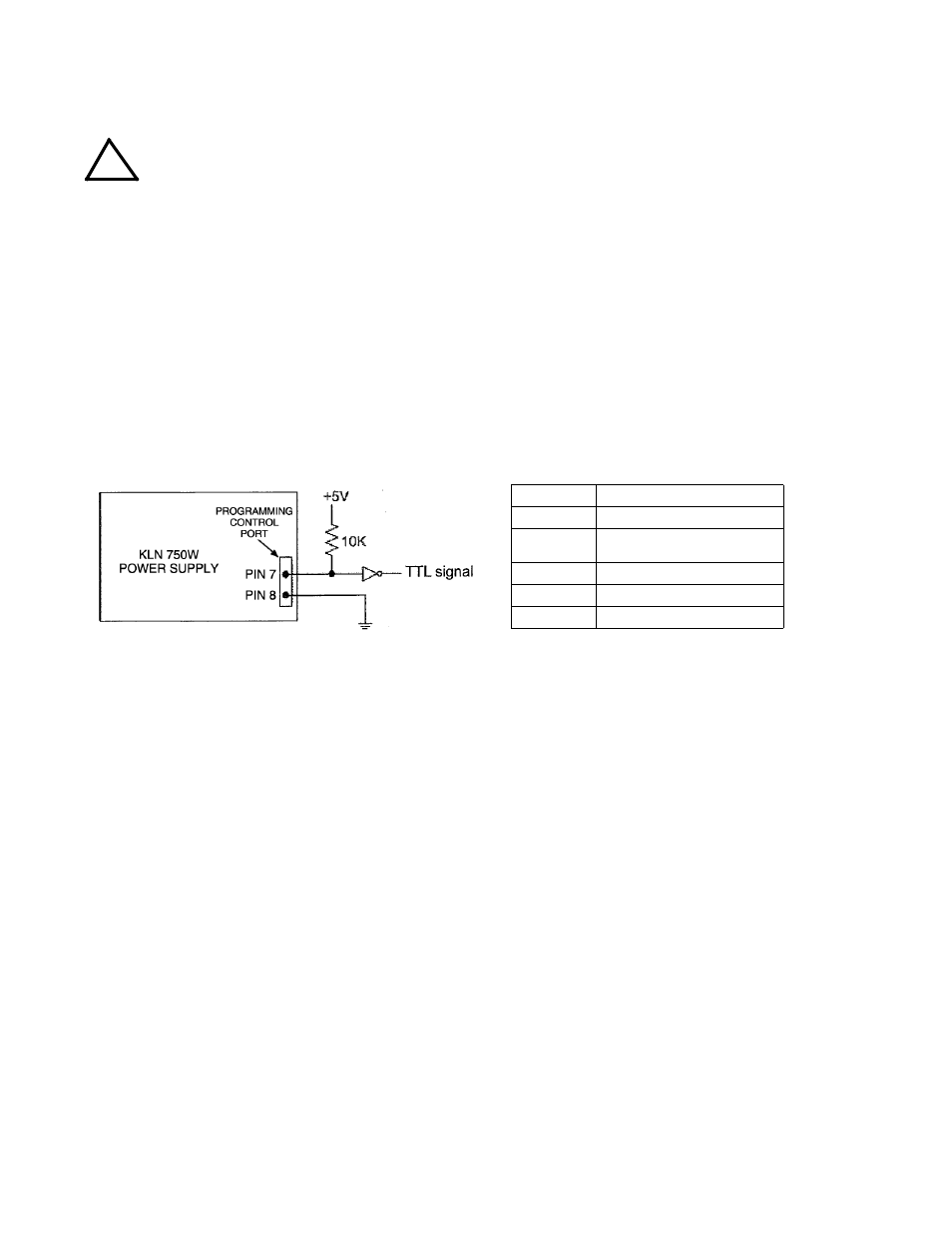
The following status signals are open collector TTL signals via an optocoupler referenced to
Programming Control port pin 8: maximum voltage is 30V, maximum current is 8mA. See Figure
3-4. Status noted in Figure 3-4 is present when signal is TTL high, absent when TTL low.
FIGURE 3-4. PROGRAMMING CONTROL PORT STATUS MONITORING
3.6
DIGITAL REMOTE MODE PROGRAMMING
KLN 750W models may be digitally programmed over a control bus using SCPI (Standard Com-
mands for Programmable Instruments). SCPI provides a common language conforming to IEEE
488.2 for instruments used in an automatic test system (see PAR. 3.7). The control bus used
must be either the IEEE 488 standard communication bus (General Purpose Interface Bus,
GPIB), or the RS-485 Serial Bus.
Refer to Table 2-3 for input/output signal allocations for communication via the GPIB and Table
2-2 for RS-485.
This section includes required setup for GPIB (address) and RS-485 (address and baud rate)
(PAR. 3.6.3.1), a discussion of GPIB bus protocols (PAR. 3.6.3.1) followed by a detailed expla-
nation of SCPI programming (PAR. 3.7).
!
STATUS PIN
DESCRIPTION
7
Unit power on
9
Alarm (OVP, OCP or output shut-
down applied to pin 23)
10
Output on
11
Constant Current (CC)
12
Constant Voltage (CV)