7 load connection using remote sensing, Load connection using remote sensing -10 – KEPCO KLN 750W Series, Firmware Version 1.60 to 1.6x User Manual
Page 30
2-10
KLN 750W 032614
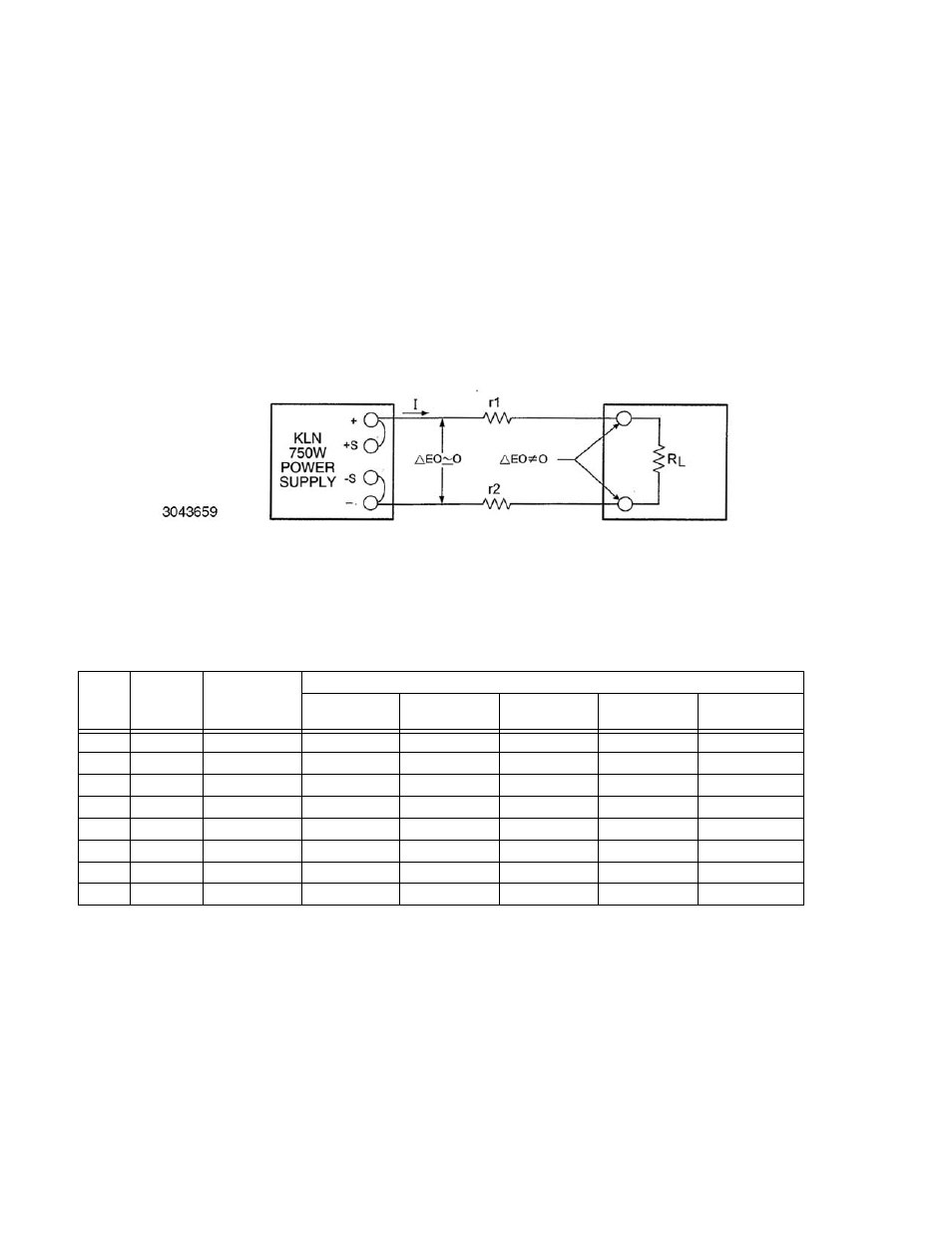
Use the following formula and Figure 2-7 to calculate the voltage drop based on expected cur-
rent and wire resistance. Refer to Table 2-5 for wire resistance for standard AWG sizes, as well
as maximum recommended length of load wires for a voltage drop of less than 1V with expected
load current of 5, 10, 20, 50 or 150 Amperes.
V
DROP
= (I x r1) + (I x r2)
where r1 and r2 is the load wire resistance
I is output current
Voltage across Load RL = Voltage (displayed on front panel display) – V
DROP
FIGURE 2-7. LOAD WIRE VOLTAGE DROP, EQUIVALENT SCHEMATIC DIAGRAM
2.5.7
LOAD CONNECTION USING REMOTE SENSING
Figure 2-8 shows a typical configuration using remote sensing.
Use #22 AWG wire, twisted
pair for remote sense connections. Table 2-5 shows typical load wire length, AWG wire size
and load current required for a voltage drop of less than 1V. Table 1-1 lists the maximum
voltage drop compensation for each model that will allow voltage measured at the load to
be the same as the voltage shown on the front panel display.
TABLE 2-5. MAXIMUM LOAD WIRE LENGTH FOR VOLTAGE DROP LESS THAN 1V
AWG
SIZE
Wire
Diameter
mm2
Resistance*
(Ohm/100m)
Maximum Load Wire Length for Voltage drop less than 1V
Load Current
5A
Load Cur-
rent 10A
Load Current
20A
Load Cur-
rent 50A
Load Current
150A
14
2
0.8
24.4m
12.2m
6.1m
2.4m
0.6m
12
3.5
0.5
36.6m
18.3m
9.1m
3.7m
1.0m
10
5.5
0.3
61.0m
30.5m
15.2m
6.1m
1.8m
8
8
0.2
97.5m
48.8m
24.4m
9.8m
3.0m
6
14
0.1
152.4m
61m
38.1m
15.2m
4.9m
4
22
0.1
243.8m
121.9m
61.0m
24.4m
7.9m
2
38
0.1
365.7m
182.9m
91.4m
38.1m
12.2m
0
60
0.0
696m
304.8m
152.4m
61.0m
20.7m
* Values shown are rounded up.