Figure 2-8. load connections, remote sensing, 6 cooling, 7 setting up the unit – KEPCO KLN 750W Series, Firmware Version 1.60 to 1.6x User Manual
Page 31: 1 setup for local operation, 2 setup for remote operation via rs-485, Cooling -11, Setting up the unit -11, Setup for local operation -11, Setup for remote operation via rs-485 -11, Load connections, remote sensing -11
KLN 750W 032614
2-11
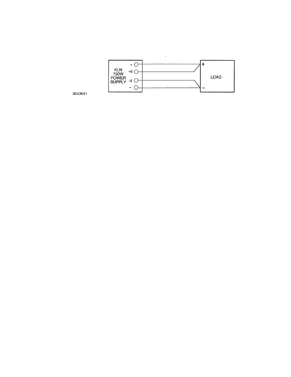
CAUTION: CONNECT +S ONLY TO + AND –S ONLY TO –. CONNECTING +S TO –S, +V
TO –S, OR –V TO +S WILL DAMAGE THE UNIT.
FIGURE 2-8. LOAD CONNECTIONS, REMOTE SENSING
2.6
COOLING
The power devices used within the power supply are maintained within their operating tempera-
ture range by means of internal heat sink assemblies and a variable speed fan with air flow from
front to back. There are no intake or exhaust ports at the top or bottom, permitting stacked rack
mounting with no air gaps between stacked units. If the power supply is located within a confined
space, take care that the ambient temperature, which is the temperature of the air immediately
surrounding the power supply, does not rise above the specified limits (see Table 1-2).
2.7
SETTING UP THE UNIT
The following paragraphs describe the connections and initial KLN 750W setup needed to oper-
ate in the desired mode.
2.7.1
SETUP FOR LOCAL OPERATION
After connecting the unit using either local (PAR. 2.5.7) or remote sensing (PAR. 2.5.7), the unit
will power up in Local mode with no further setup required.
2.7.2
SETUP FOR REMOTE OPERATION VIA RS-485
CAUTION: DO NOT CONNECT THE POSITIVE OUTPUT TO GROUND WHEN RS-485 IS
USED. THERE IS A POTENTIAL SHOCK HAZARD AT THE RS-485 PORT
WHEN POWER SUPPLIES ARE USED WITH RATED OR COMBINED VOLT-
AGE GREATER THAN 400V AND THE POSITIVE OUTPUT OF THE POWER
SUPPLY IS GROUNDED.
Connect the KLN 750W to the controlling computer or to the previous unit in the RS-485 daisy
chain per Figure 2-9. It is recommended that double shielded wire be used to ensure the quality
of remote communication. The last unit on the RS-485 bus requires a 120-Ohm terminating
resistor as shown in Figure 2-9.
With all power off, connect the load to the KLN 750W using either local or remote sensing (refer
to PAR. 2.5). If units are to be connected in series or parallel, refer to PAR. 2.8.
Turn power on and refer to PAR. 3.2 for power supply basics. See PAR. 3.3.16 to establish RS-
485 baud rate and PAR. 3.3.18 to establish the RS-485 Address.
SCPI programming is described in PAR. 3.7; Appendices A and B provide syntax for SCPI com-
mon and subsystem commands and queries implemented in this unit. For RS-485 communica-