Figure 3-2. 7-segment display characters, 1 turning the power supply on, Turning the power supply on -3 – KEPCO KLN 750W Series, Firmware Version 1.60 to 1.6x User Manual
Page 39: Segment display characters -3, R 3.2.1)
KLN 750W 032614
3-3
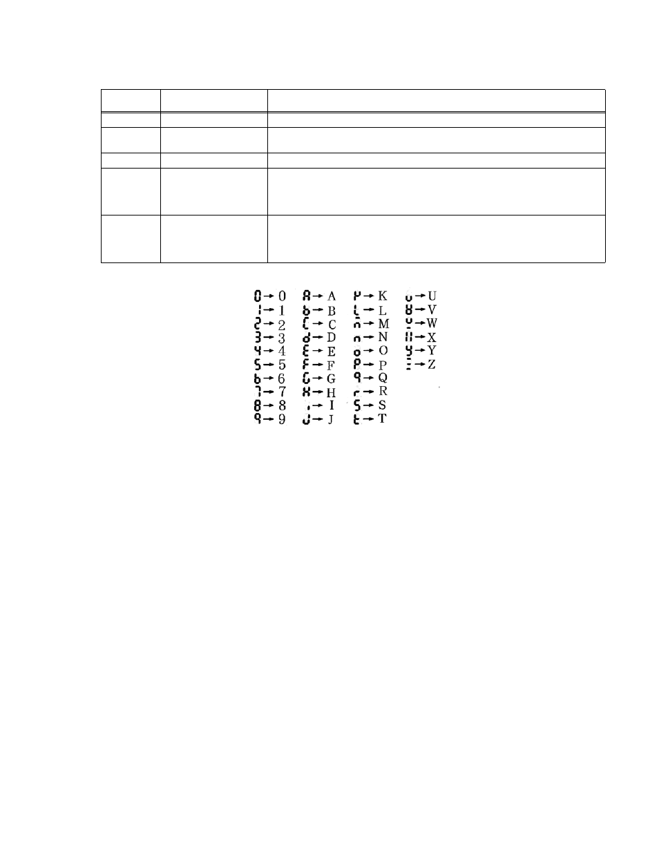
FIGURE 3-2. 7-SEGMENT DISPLAY CHARACTERS
3.2.1
TURNING THE POWER SUPPLY ON
1. To turn the power supply on, set POWER ON/OFF circuit breaker (1, Figure 2-1) to ON.
Apply firm, continuous pressure to rocker actuator until fully engaged.
2. When the power supply is turned on, it beeps and performs a self-test which sequentially
checks the power status, PFC module (DC bus voltage), A/D converter, display board,
SENSE status, and EEPROM.
3. While the self-test is in process, the following occurs:
• For 1 second all the indicators on the front panel are lit.
• For 1.6 seconds the Voltage display shows rated voltage and the Current display
shows rated current. The rest of the indicators are unlit and the digital and analog inter-
faces are temporarily disabled.
• For 1.2 seconds the Voltage display shows Hx.xx (hardware version) and the Current
display shows Fx.xx (firmware version). The rest of the indicators are still unlit.
• For 1.2 seconds the Voltage display shows Ax.xx (A/D converter version) and Current
display shows Dx.xx (display board version). The rest of the indicators are still unlit.
15
CC indicator
Lights when unit is in Constant Current mode
16
OVP indicator
Overvoltage Protection indicator. Lights if overvoltage error has occurred. Blinks while
setting overvoltage protection value.
17
CV indicator
Lights when unit is in Constant Voltage mode
18
Current Display
4 digit LED
Displays output current or setting value in Amperes. CC indicator at right lights when
unit is in constant current mode. OCP indicator lights if overcurrent error has
occurred. OCP blinks while setting OCP value. Refer to Figure 3-2 to translate limited
7-segment display characters into standard alphanumeric characters.
19
Voltage Display
4 digit LED
Displays output voltage or setting value in Volts. CV indicator at right lights when unit
is in constant voltage mode. OVP indicator lights if overvoltage error has occurred.
OVP blinks while setting OVP value. Refer to Figure 3-2 to translate limited 7-seg-
ment display characters into standard alphanumeric characters.
TABLE 3-1. FRONT PANEL CONTROLS AND INDICATORS (CONTINUED)
NUMBER
(FIGURE 3-1)
CONTROL/INDICATOR
FUNCTION