Figure 2-3. programming control port, Programming control port -3, Programming control port i/o pin assignments -3 – KEPCO KLN 750W Series, Firmware Version 1.60 to 1.6x User Manual
Page 23: R. 2.3, Able 2-4 for pin assignmen
KLN 750W 032614
2-3
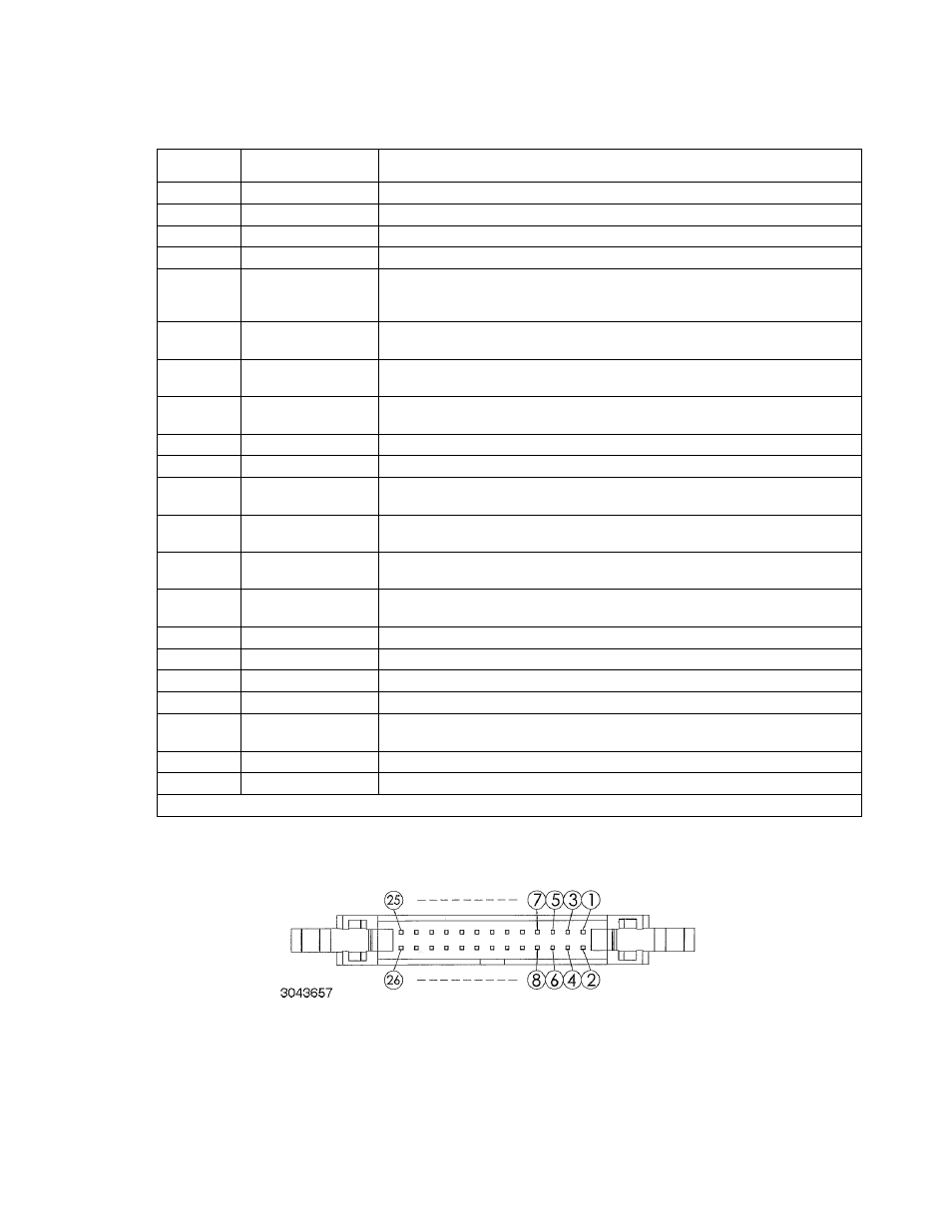
FIGURE 2-3. PROGRAMMING CONTROL PORT
TABLE 2-4. PROGRAMMING CONTROL PORT I/O PIN ASSIGNMENTS
PIN
SIGNAL NAME
FUNCTION
1, 2
RECALL
External recall control (dry contact). Same function as RCL key on front panel.
3, 4, 5, 6
---
Not used
7
Power on/off status
Output signal. Active (low between pin 7 and pin 8) to indicate unit is turned on. (1)
8
Status common
Common for Status signal pins 7, 9, 10, 11 and 12 (1)
9
Alarm status
Output signal. Active (low between pin 9 and pin 8) to indicate whether alarm (OVP or
OCP trips or shutdown signal applied to pin 23) has occurred. (open collector via opto-
coupler). (1)
10
On/off status
Output signal. Active (low between pin 10 and pin 8) to indicate output is on (open col-
lector by optocoupler). (1) (See PAR. 3.3.25 to enable.)
11
CC status
Output signal. Active (low between pin 11 and pin 8) to indicate unit is in constant cur-
rent mode (open collector by optocoupler). (1)
12
CV status
Output signal. Active (low between pin 12 and pin 8) to indicate unit is in constant volt-
age mode (open collector by optocoupler). (1)
13
EXT 5V input+
Input signal. Used to supply +5V for the relay providing remote output on/off function.
14
EXT V input common
Common for Pin 13 (remote output on/off function).
15
PRL IN+
Input signal. For units operating in parallel, used for signal input into MASTER of cur-
rent sharing between MASTER and SLAVE(s) (see PAR. 2.8.2.1).
16
EXT CV
Input signal. External voltage to control output voltage of unit. 0 to 10V d-c corre-
sponds to zero to full scale output voltage (see PAR. 3.3.26 to enable).
17
PRL OUT+
Output signal. For units operating in parallel, used for signal output of current sharing
from SLAVE to MASTER (see PAR. 2.8.2.1).
18
EXT CC
Input signal. External voltage to control output current of unit. 0 to 10V d-c corre-
sponds to zero to full scale output current (see PAR. 3.3.27 to enable).
19
PRL IN–/OUT–
V common for pins 15 and 17.
20
V Monitor
Output signal. Zero to 10V d-c corresponds to zero to full scale voltage,
21
ON/OFF Control
Input Signal. Used to power unit on (short) or off (open). Dry contact.
22
A Monitor
Output signal. Zero to 10V d-c corresponds to zero to full scale current.
23
Shutdown
Short between pin 23 and analog ground (pins 24 or 26) causes emergency shutdown
of unit.
24, 26
Analog Common
Analog signal control ground, connected to pin 19.
25
Digital Common
Digital signal control ground.
(1) Open collector output: maximum voltage 30V, maximum current 8mA; Low: <0.4V.