2 remote emergency shutdown, Remote emergency shutdown -23, Ar. 3.5.3) – KEPCO KLN 750W Series, Firmware Version 1.60 to 1.6x User Manual
Page 59: Ar. 3.5.6)
KLN 750W 032614
3-23
3.5.2
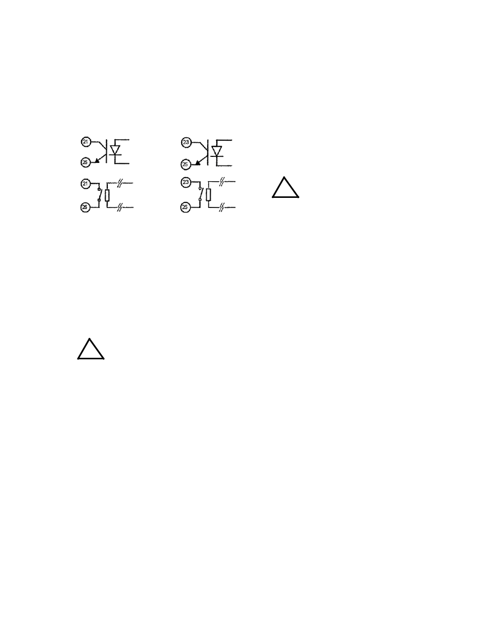
REMOTE EMERGENCY SHUTDOWN
Remote emergency shutdown of the output can be accomplished using Programming Control
port pins 23 and 25. When the pins are open, operation is normal. When they are shorted, the
output is immediately set to off. This can be accomplished using either an optocoupler or relay.
(See Figure 3-3).
FIGURE 3-3. REMOTE CONTROL USING PROGRAMMING CONTROL PORT AND OPTOCOUPLER OR RELAY
3.5.3
REMOTE CONTROL OF OUTPUT VOLTAGE USING AN ANALOG SIGNAL
Connect an analog voltage, adjustable from 0 to +10V d-c (corresponding to 0 to rated output
voltage) between pin 16 (+) and pin 26 (–) of the Programming Control Port. The analog voltage
will control the output only after the function is enabled by setting Constant Voltage control to
EXT from the front panel (see PAR. 3.3.26).
CAUTION: TO AVOID OVP FROM TRIPPING WHEN THE OUTPUT IS SET TO ON, THE
ANALOG PROGRAMMING VOLTAGE MUST NOT EXCEED 10.5V D-C.
3.5.4
REMOTE CONTROL OF OUTPUT CURRENT USING AN ANALOG SIGNAL
Connect an analog voltage, adjustable from 0 to +10V d-c (corresponding to 0 to rated output
current) between pin 18 (+) and pin 26 (–) of the Programming Control Port. The analog voltage
will control the output only after the function is enabled by setting Constant Current control to
EXT from the front panel (see PAR. 3.3.27).
CAUTION: TO AVOID OCP FROM TRIPPING WHEN THE OUTPUT IS SET TO ON, THE
ANALOG PROGRAMMING VOLTAGE MUST NOT EXCEED 10.5V D-C.
3.5.5
RECALLING PREVIOUSLY STORED SETTING USING PROGRAMMING CONTROL PORT
Connect a switch or relay (dry contactor) across pins 1 and 2 of the Programming Control Port.
Each time the pins are shorted together is equivalent to pressing the RCL key (see PAR. 3.3.7).
Closures of the switch or relay can be used to select the desired memory cell.
3.5.6
MONITORING OUTPUT STATUS USING PROGRAMMING CONTROL PORT
The Programming Control port allows monitoring of output voltage and current, operating mode
(CC or CV), power on/off, output on/off and alarm status (occurrence of OVP, OCP, or output
shutdown).
EMERGENCY SHUTDOWN
PINS 23 AND 25
NOTES:
1.
Control can be either by optocoupler or
relay.
2.
Recommended that contacts be posi-
tioned as close to pins as possible.
CAUTION:
Observe proper polarity.
!
OUTPUT ON/OFF
PINS 21 AND 25
!