Figure 2-2. rs-485 port, Rs-485 port -2, Rs-485 port input/output pin assignments -2 – KEPCO KLN 750W Series, Firmware Version 1.60 to 1.6x User Manual
Page 22: Able 2-2 for, E 2-3 for
2-2
KLN 750W 032614
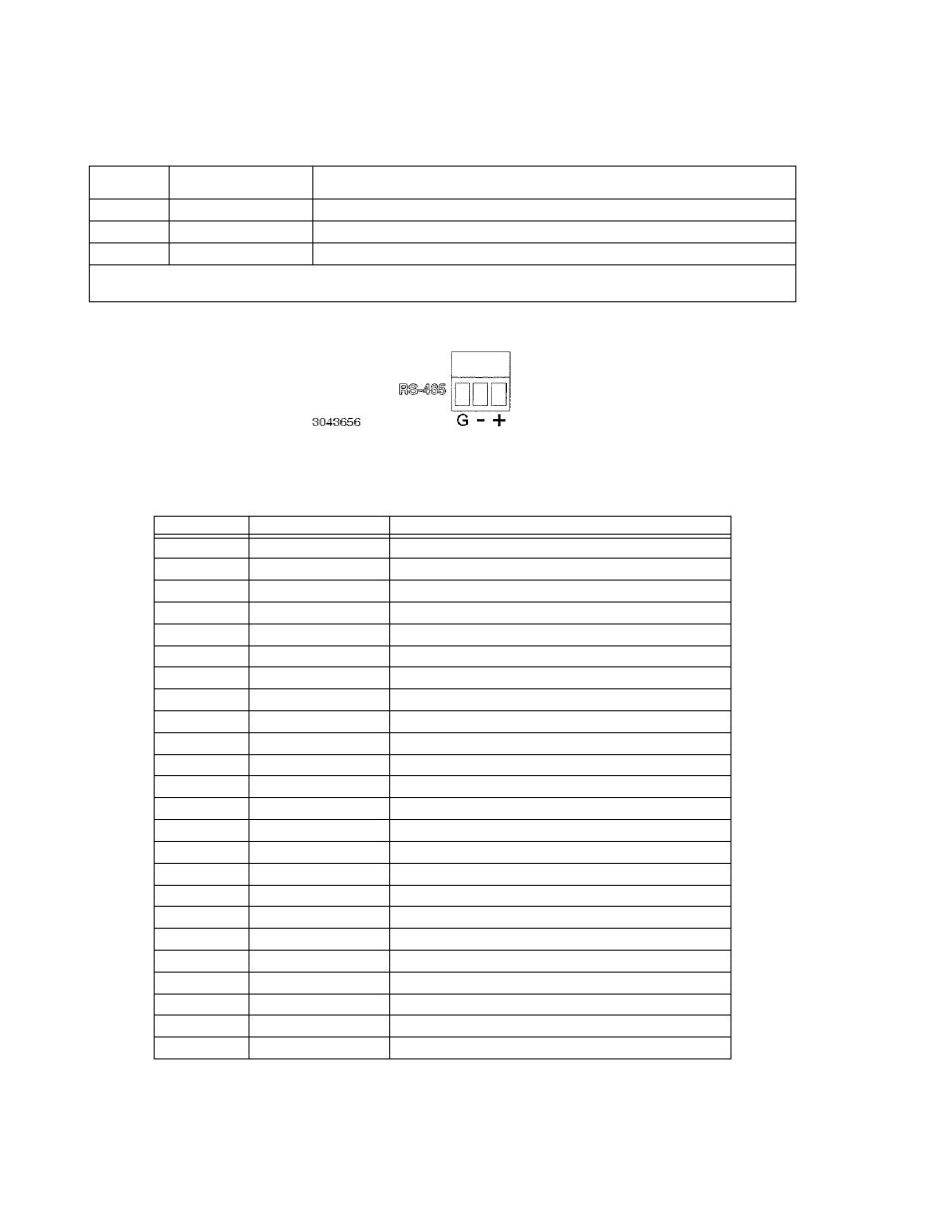
FIGURE 2-2. RS-485 PORT
TABLE 2-2. RS-485 PORT INPUT/OUTPUT PIN ASSIGNMENTS
PIN
(FIGURE 2-2)
SIGNAL NAME
FUNCTION
G
Ground
Reduce external interference
+
+RX
Connect to +TX of computer and/or +RX of next unit on RS-485 bus (see Figure 2-9).
–
–RX
Connect to –TX of computer and/or –RX of next unit on RS-485 bus (see Figure 2-9).
NOTE: Connect 120 Ohm termination resistor across + and – of last unit connected to RS-485 bus (furthest from computer)
See PAR. 2.7.2.
TABLE 2-3. GPIB (IEEE 488) PORT INPUT/OUTPUT PIN ASSIGNMENTS
PIN
SIGNAL NAME
FUNCTION
1
D
I
01
I/O Line
2
D
I
02
I/O Line
3
D
I
03
I/O Line
4
D
I
04
I/O Line
5
EOI
End or Identify
6
DAV
Data Valid
7
NRFD
Not Ready for Data
8
NDAC
Not Data Accepted
9
IFC
Interface Clear
10
SRQ
Service Request
11
ATN
Attention
12
SHIELD
Shield
13
D
I
05
I/O Line
14
D
I
06
I/O Line
15
D
I
07
I/O Line
16
D
I
08
I/O Line
17
REN
Remote Enable
18
GND
Ground (signal common)
19
GND
Ground (signal common)
20
GND
Ground (signal common)
21
GND
Ground (signal common)
22
GND
Ground (signal common)
23
GND
Ground (signal common)
24
LOGIC GND
Logic Ground