Section 2 - installation, 1 unpacking and inspection, 2 terminations and controls – KEPCO KLN 750W Series, Firmware Version 1.60 to 1.6x User Manual
Page 21: Figure 2-1. kln 750w series rear panel, Table 2-1. rear panel connector functions, Unpacking and inspection -1, Terminations and controls -1, Kln 750w series rear panel -1, Rear panel connector functions -1
KLN 750W 032614
2-1
SECTION 2 - INSTALLATION
2.1
UNPACKING AND INSPECTION
This instrument has been thoroughly inspected and tested prior to packing and is ready for
operation. After careful unpacking, inspect for shipping damage before attempting to operate.
Perform the preliminary operational check as outlined in PAR. 2.3. If any indication of damage is
found, file an immediate claim with the responsible transport service.
2.2
TERMINATIONS AND CONTROLS
a) Front Panel: Refer to Figure 3-1 and Table 3-1.
b) Rear Panel: Refer to Figure 2-1 and Table 2-1.
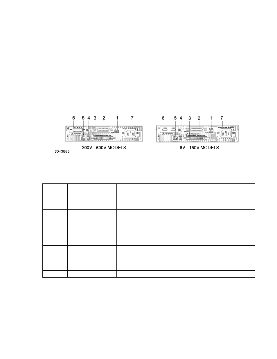
FIGURE 2-1. KLN 750W SERIES REAR PANEL
TABLE 2-1. REAR PANEL CONNECTOR FUNCTIONS
NUMBER
(FIGURE 2-1)
CONNECTOR/TERMINAL
FUNCTION
1
RS-485
3-pin pluggable terminal
block
Allows connection to RS-485 bus. See Table 2-2 for details.
2
Optional:
either 24-pin GPIB
connector (shown)
or LAN ethernet connector
(not shown)
Allows connection to GPIB bus or LAN (optional) when installed. See Table 2-3 for
GPIB connector details.
3
Programming Control Port
Allows access to analog input/output signals that allow monitoring and control of the
power supply by analog means. See Table 2-4 for pin assignments.
4
SER IN
Provides output voltage reference from master to slave to ensure voltage slave
matches the master when two units connected in series.
5
+S, –S
Remote sensing voltage compensation.
6
DC Output
Allows connection to load.
7
AC input
Allows connection to mains supply using power cord supplied.