4 sealing the connection area, 5 starting up the inverter, 1 switching on the inverter – KACO Powador 16.0 TR3 User Manual
Page 26
I n s t a l l i n g t h e I n v e r t e r
Operating Instructions Powador 16.0 TR3, 18.0 TR3_EN
Page 27
Authorised electrician
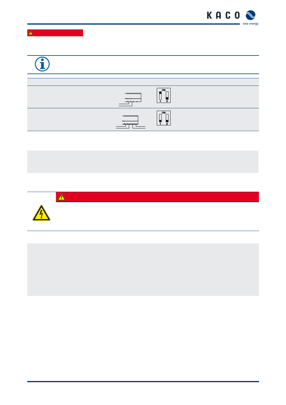
7.3.5.2 Activating the terminating resistor (switches 1 and 2 on the connection circuit board)
Activate the terminating resistor in the inverter that represents the terminal unit within your wiring diagram.
NOTICE
Always activate the terminating resistor in the terminal unit using the left DIP switch (1).
Sample connection
DIP switch
Switch 1
Switch 2
The inverter is the terminal unit:
Activate R
a
A B A B
ON
OFF
The inverter is not the terminal unit:
Deactivate R
a
A B A B
OFF
OFF
7.4
Sealing the connection area
1.
Place the grounding cable lug on the grounding point of the housing.
2. Place the connection cover on the connection area of the inverter.
3. Screw in the four Torx screws on the front side of the connection cover (blue).
7.5
Starting up the inverter
DANGER
Lethal voltages are still present in the terminals and leads of the inverter even after the
inverter has been switched off and disconnected.
Severe injuries or death if the leads and terminals in the inverter are touched.
Only authorised electricians who are approved by the supply grid operator may start up the inverter.
7.5.1
Switching on the inverter
↻ The inverter has been mounted and electrically installed.
↻ The cover for the connection area is grounded and closed.
↻ The PV generator is supplying a voltage > 200 V.
1.
Connect the grid voltage using the external circuit breakers.
2. Connect the PV generator using the DC disconnect (0 → 1).
»
The inverter begins to operate.
»
During the initial start-up: Follow the instructions of the New Connection Wizard (see section 8.2 on page 31).