1 connecting the ethernet interface – KACO Powador 16.0 TR3 User Manual
Page 23
I n s t a l l i n g t h e I n v e r t e r
Page 24
Operating Instructions Powador 16.0 TR3, 18.0 TR3_EN
Authorised electrician
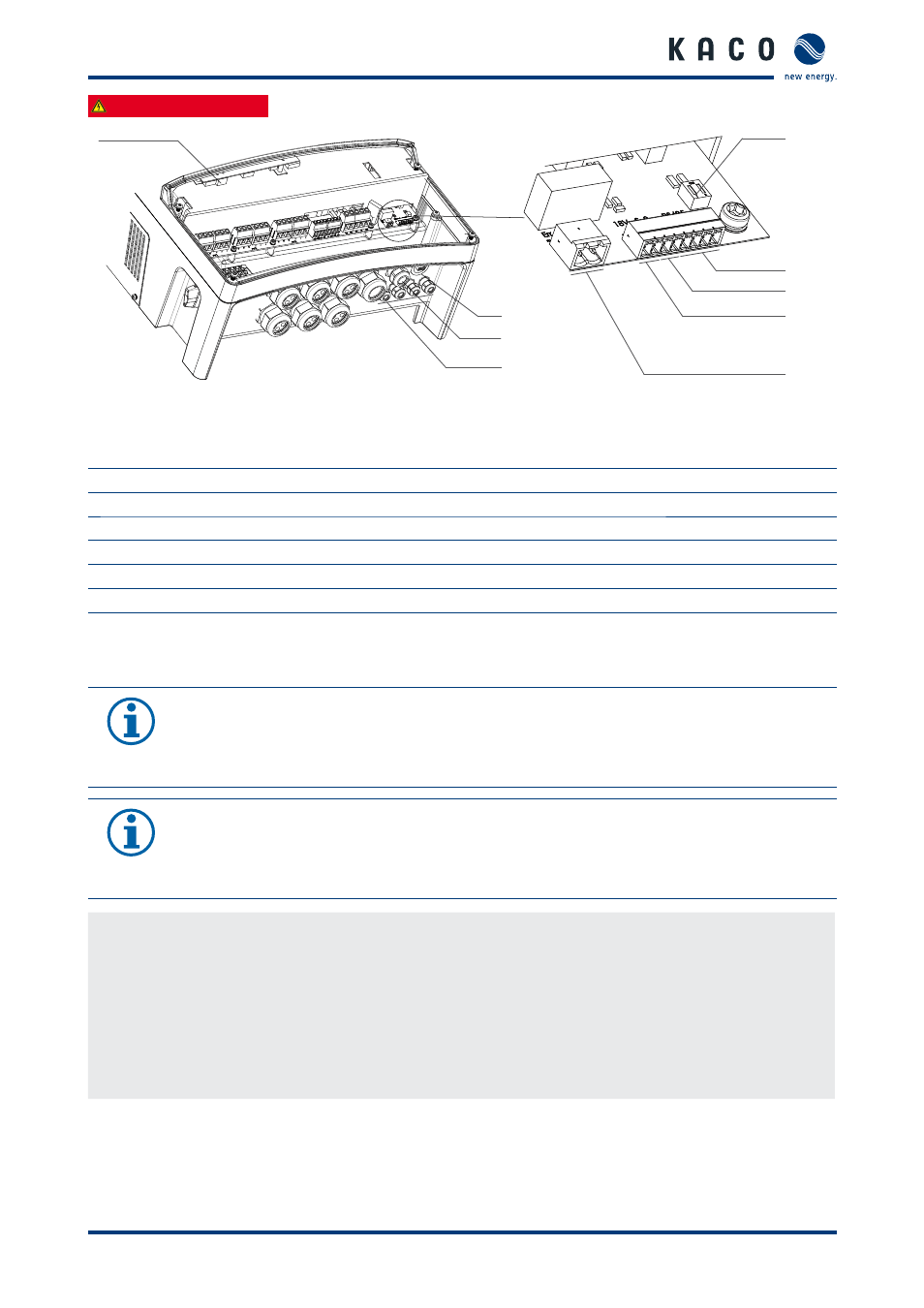
Fig. 10:
Connection area: connecting the interfaces
Key
1
Ethernet interface
5
Connection for the fault signal relay
2
Cable fi ttings (M16) for interface connections
6
18 V output
3
Cable fi tting (M25) for Ethernet cable
7
S0 output
4
USB interface with cover
8
RS485 interface
9
DIP switch for terminating resistor R
a
7.3.1
Connecting the Ethernet interface
NOTICE
The connection plug of an RJ45 cable is larger than the opening of an M25 cable fi tting when it is
installed. For this reason, remove the sealing insert before installation and thread the Ethernet cable
outside of the cable fi tting through the sealing insert.
NOTICE
Use a suitable category 5 network cable. The maximum length of a network segment is 100 m.
Ensure that the cable is correctly assigned. The Ethernet connection of the inverter supports auto-
sensing. You can use both crossed and 1:1 Ethernet connection cables.
Connecting an Ethernet cable to the inverter
1.
Unscrew the cable fi tting (see fi gure 10 on page 24) and remove the lock.
2. Remove the sealing insert from the cable fi tting.
3. Thread the Ethernet cable through the lock of the cable fi tting and the sealing insert.
4. Thread the Ethernet cable through the cable fi tting inside the housing.
5. Connect the Ethernet cable to the Ethernet interface (see fi gure 10 on page 24).
6. Insert the sealing insert into the cable fi tting.
7.
Attach and tighten the lock of the cable fi tting.
5
7
8
9
6
1
4
2
3