1 connecting the inverter to the power grid – KACO Powador 16.0 TR3 User Manual
Page 19
Page 20
Operating Instructions Powador 16.0 TR3, 18.0 TR3_EN
Authorised electrician
I n s t a l l i n g t h e I n v e r t e r
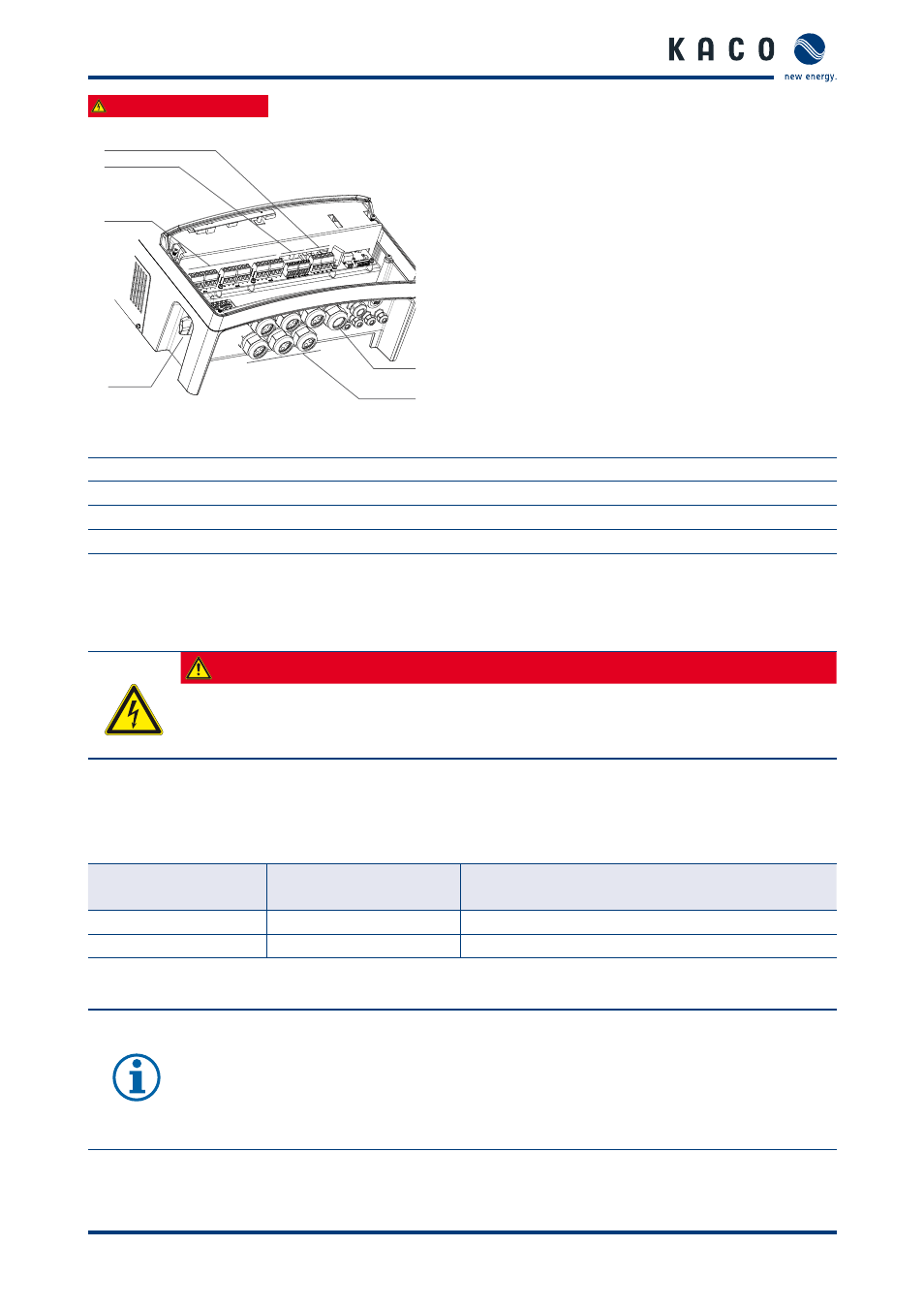
Fig. 7:
Connection area: Electrical connection
Key
1
DC connection terminals
4
DC disconnect
2
Grounding terminals for PV generator
5
Cable fi tting (M40) for DC connection
3
AC connection terminals
6
Cable fi tting (M40) for AC connection
7.2.1
Connecting the inverter to the power grid
The grid connection leads are connected on the right in the connection area (see fi gure 7).
DANGER
Risk of fatal injury due to electric shock
Severe injuries or death will result if the live connections are touched.
›
Disconnect the inverter from all power sources before you insert the grid power lead into the unit.
Recommended conductor cross-sections and fuse protection of NYM leads for fi xed wiring according to
VDE 0100 part 430
For lead lengths up to 20 m, use the conductor cross-sections listed in table 4. Longer lead lengths require larger
conductor cross-sections.
Model
Conductor cross-
section
Fuse protection: NEOZED safety fuses gL
or comparable automatic circuit breakers
Powador 16.0 TR3
6.0 mm²
35 A for 6.0 mm² conductor cross-section
Powador 18.0 TR3
6.0 mm²
35 A for 6.0 mm² conductor cross-section
Table 4:
Recommended conductor cross-sections and fuse protection of NYM leads
NOTICE
When the lead impedance is high (i.e. long grid-side leads), the voltage at the grid terminals of the
inverter will increase during feed-in to the grid. The inverter monitors this voltage. If it exceeds the
country-specifi c line overvoltage limit value, the inverter switches off .
›
Ensure that the lead cross-sections are suffi
ciently large or that the lead lengths are suffi
ciently
short.
3
2
1
6
5
4