KACO Powador 16.0 TR3 User Manual
Page 20
I n s t a l l i n g t h e I n v e r t e r
Operating Instructions Powador 16.0 TR3, 18.0 TR3_EN
Page 21
Authorised electrician
Making the grid connection
↻ Use leads with fi ve wires (L1, L2, L3, N, PE).
1.
Unscrew the cable fi tting.
2. Remove the outer cladding of the AC leads.
3. Insert the AC leads through the cable fi tting into the connection area.
4. Strip the insulation from the AC leads.
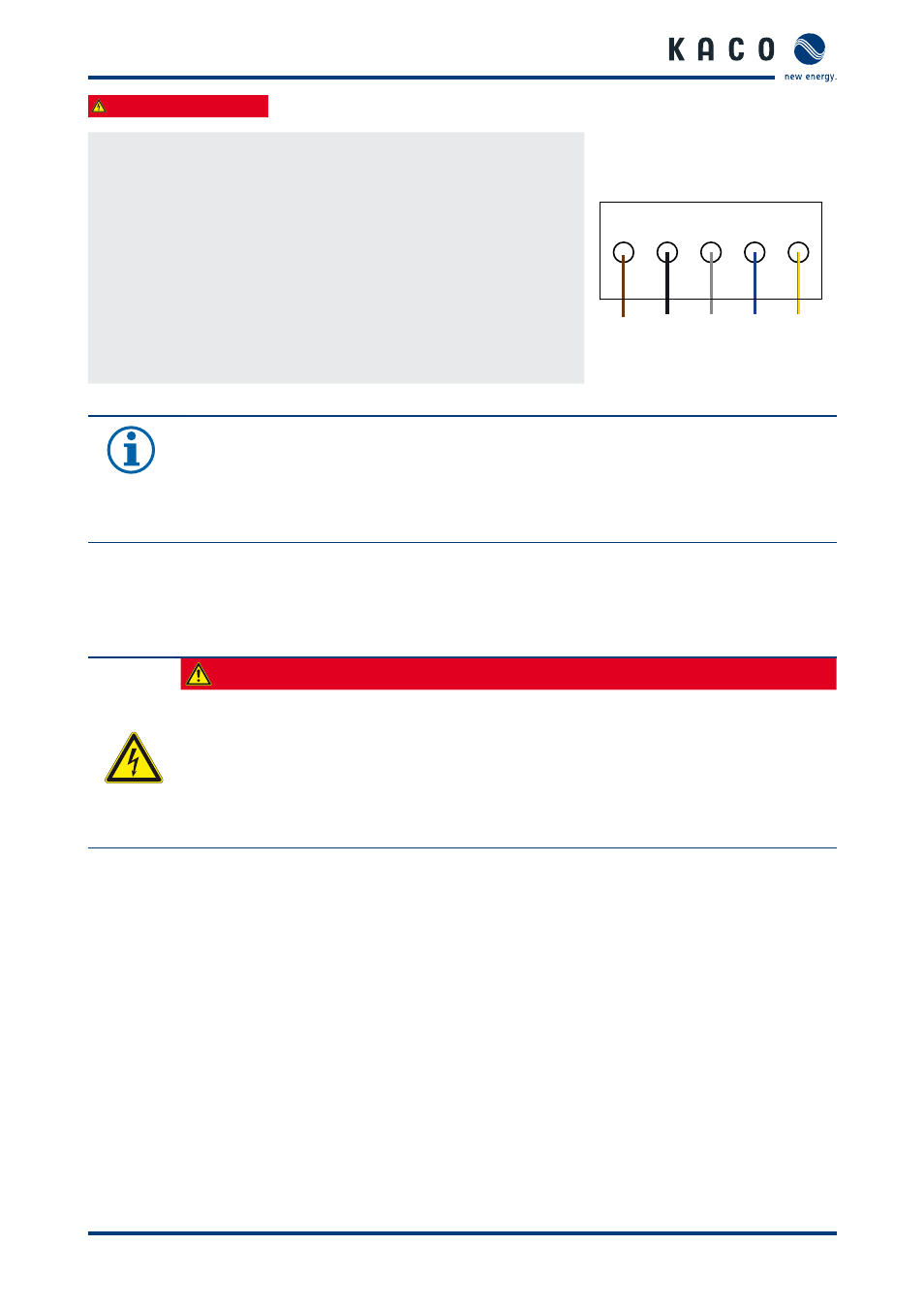
5. Connect the leads according to the labelling of the PCB terminals
(fi gure 8 on page 21).
6. Check that all connected leads are tightly seated.
7.
Tighten the cable fi tting.
L1 L2
N
PE
BK
BU GNYE
BN
L3
GY
»
The inverter is now connected to the power grid.
Fig. 8:
AC connection terminals
NOTICE
An AC-side disconnection unit must be provided in the fi nal installation. This disconnection unit
must installed in such a manner that it can be accessed at any time without hindrance.
If a residual current circuit breaker is necessary due to the installation specifi cation, a type “A” AFI
(AC/DC-sensitive residual current circuit breaker) must be used.
7.2.2
Connecting the PV generator
Connect the PV generator in the connection area left. Use the cable fi ttings provided (see fi gure 7 on page 20).
DANGER
Risk of fatal injury due to contact voltages.
›
During installation: Electrically disconnect the DC positive and DC negative from the protective
earth (PE).
Removing the plug connection without previously disconnecting the inverter from the
PC generator can result in a hazard to health and damage to the inverter.
›
Disconnect the inverter from the PV generator by actuating the integrated DC disconnector.
›
Remove the plug connector.