4 mechanical components, 5 interfaces – KACO Powador 16.0 TR3 User Manual
Page 10
D e s c r i p t i o n
Operating Instructions Powador 16.0 TR3, 18.0 TR3_EN
Page 11
IT
Country-specifi c function
3.2.3.4 Self-test in accordance with ENEL grid connection guide, Ed. 2.1
NOTICE
The tests should, if necessary, be conducted by the gird operator. You activate the self test in the
parameter menu during feed-in operation (see section 8.3 on page 31). The self-test presumes that
the inverter is already feeding into the grid, so that the shutdown condition can be simulated.
Do not press the control keys of the inverter during the self-test.
Method in which the shutdown test proceeds:
The stored undervoltage cut-off limit is increased by means of a software ramp function. The ramp
function has a gradient of 5 V/s. The software increases the undervoltage cut-off limit for as long as
the inverter is feeding into the grid according to the specifi ed ramp function. As soon as the inverter
switches off , the software automatically calculates the cut-off limit. The calculated cut-off limit, as well
as the cut-off time and the type of test, are transmitted via the RS485 interface to a terminal program.
The subsequent overvoltage shutdown test is started automatically. This test runs according to the
same design as the undervoltage shutdown test.
Frequency is also measured with the procedure described here. In this case, a software ramp function
with a gradient of 0.05 Hz/s is used. The result of the entire test is sent to the terminal program at the
end of the test, as well as being in the display of the inverter. If a test fails, the entire test is cancelled
and a corresponding message is issued. The test can subsequently be repeated.
KACO recommends the Tera Term terminal program. This software, off ered as freeware, is able to
output the results of the shutdown test in a text fi le. A PDF fi le that also contains a date and time
stamp can then be created from this text fi le.
The self test runs automatically and can last several minutes. After the self test fi nishes successfully,
the unit restores the previously set switch-off values. The inverter automatically starts the feed-in
process.
3.2.4 Mechanical
components
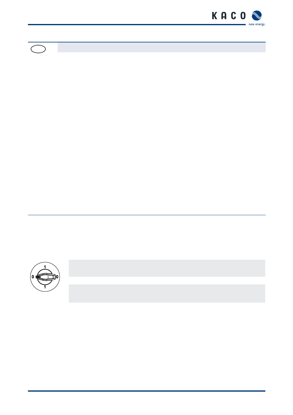
3.2.4.1 DC
disconnect
The DC disconnect is located on the left side of the inverter housing. The DC disconnect is used to disconnect the
inverter from the PV generator in order to carry out service.
Disconnecting the inverter from the PV generator
Switch the DC disconnect from 1 (ON) to 0 (OFF).
Connecting the inverter to the PV generator
Switch the DC disconnect from 0 (OFF) to 1 (ON).
3.2.5 Interfaces
The inverter off ers the following interfaces for communication and remote monitoring:
•
RS485 interface
•
Ethernet interface
•
USB interface
•
S0 interface
You confi gure the interfaces and the web server in the confi guration menu (see section 8.3.2 on page 32)