3 connecting the interfaces – KACO Powador 16.0 TR3 User Manual
Page 22
I n s t a l l i n g t h e I n v e r t e r
Operating Instructions Powador 16.0 TR3, 18.0 TR3_EN
Page 23
Authorised electrician
FR
GFDI (ground fault detector-interrupter)/ground fault monitoring
The inverter supports ground fault monitoring of the non-grounded pole. You can activate or deac-
tivate this option in the parameter menu (see section 8.3 on page 31).
Mounting the full bridge
↻ Determine whether the positive or negative pole is to
be grounded.
1.
Unscrew the fi ttings of the grounding terminals.
2. Plug the full bridge onto the positive or negative
grounding terminal. Example: Installation on the plus
grounding terminal (see fi gure 9 on page 23).
3. Tighten the grounding terminal fi ttings.
»
The PV generator is grounded.
4. Activate the ground fault monitor in the Settings menu
(see section 8.3 on page 31).
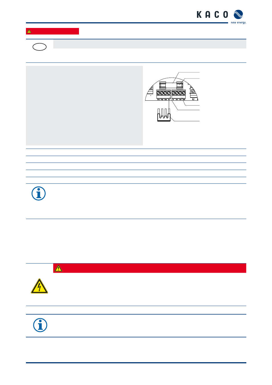
Fig. 9:
Installation of full bridge for
grounding the PV generator
Key
1
Fuse holder
4
Positive grounding terminal
2
Ground fuse
5
Full bridge for grounding the PV generator
3
Negative grounding terminal
NOTICE
If the function of ground fault monitoring is activated in the inverter, the installed fuse trips after a
ground fault in the PV system. The inverter interrupts the feed-in until the fuse has been replaced.
Use PV fuses of type URZ 10 x 38 mm 1,000 V 1 A only.
7.3
Connecting the interfaces
All interfaces, with the exception of the Ethernet interface, are located on the connection circuit board. The Ethernet
interface is located on the underside of the control circuit board. Both connection locations are located behind the
cover for the connection area. Use the cable fi ttings provided (see fi gure 10 on page 24).
DANGER
Risk of fatal injury due to electric shock
Severe injury or death from improper use of the interface connections and non-observance of
protection class III.
›
The SELV circuits (SELV: safety extra low voltage) can only be connected to other SELV circuits with
protection class III.
NOTICE
When laying the interface connection cable, note that too little clearance to the DC or AC leads can
cause interference during data transfer.
1
2
3
4
5