Cycle parameters – HEIDENHAIN TNC 620 (340 56x-02) Cycle programming User Manual
Page 97
HEIDENHAIN TNC 620
97
4.3 RIGID T
A
PPING without a Floati
ng T
a
p Holder NEW (Cy
c
le 207
,
DIN/ISO:
G207)
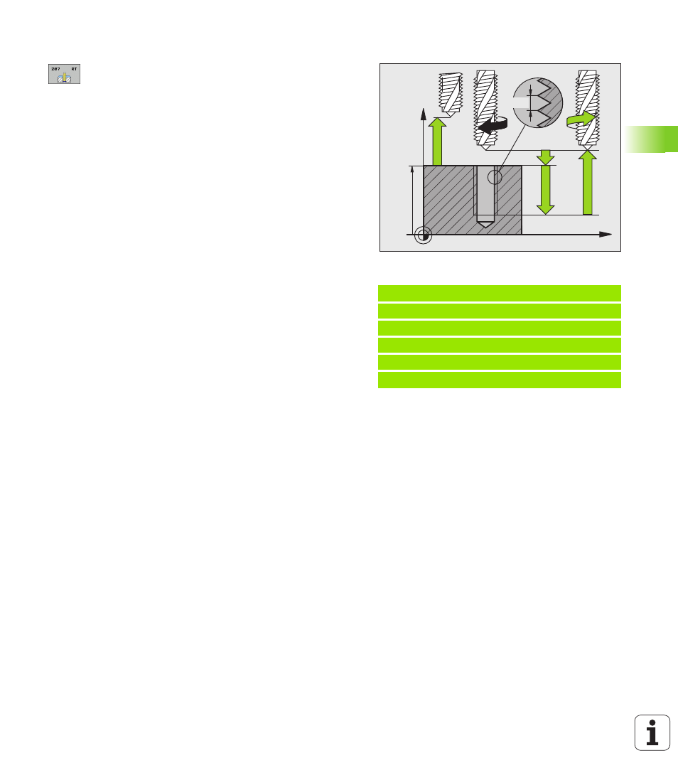
Cycle parameters
U
Setup clearance Q200 (incremental): Distance
between tool tip (at starting position) and workpiece
surface. Input range 0 to 99999.9999
U
Total hole depth Q201 (incremental): Distance
between workpiece surface and end of thread. Input
range: -99999.9999 to 99999.9999
U
Pitch Q239
Pitch of the thread. The algebraic sign differentiates
between right-hand and left-hand threads:
+ = right-hand thread
– = left-hand thread
Input range -99.9999 to 99.9999
U
Workpiece surface coordinate Q203 (absolute):
Coordinate of the workpiece surface. Input range:
-99999.9999 to 99999.9999
U
2nd setup clearance Q204 (incremental): Coordinate
in the spindle axis at which no collision between tool
and workpiece (fixtures) can occur. Input range 0 to
99999.9999
Retracting after a program interruption
If you interrupt program run during thread cutting with the machine
stop button, the TNC will display the MANUAL OPERATION soft key.
If you press the MANUAL OPERATION key, you can retract the tool
under program control. Simply press the positive axis direction button
of the active spindle axis.
Example: NC blocks
26 CYCL DEF 207 RIGID TAPPING NEW
Q200=2
;SETUP CLEARANCE
Q201=-20
;DEPTH
Q239=+1
;PITCH
Q203=+25
;SURFACE COORDINATE
Q204=50
;2ND SETUP CLEARANCE
Z
X
Q203
Q204
Q200
Q201
Q239