Cycle parameters – HEIDENHAIN TNC 620 (340 56x-02) Cycle programming User Manual
Page 138
138
Fixed Cycles: Pocket Milling / Stud Milling / Slot Milling
5.4 SL
O
T
MILLING (Cy
c
le 253, DIN/ISO: G253, A
d
v
a
nced Pr
ogr
a
mming
F
e
at
ur
es Sof
tw
a
re
Option)
Cycle parameters
U
Machining operation (0/1/2) Q215: Define the
machining operation:
0: Roughing and finishing
1: Only roughing
2: Only finishing
Side finishing and floor finishing are only executed if
the finishing allowances (Q368, Q369) have been
defined.
U
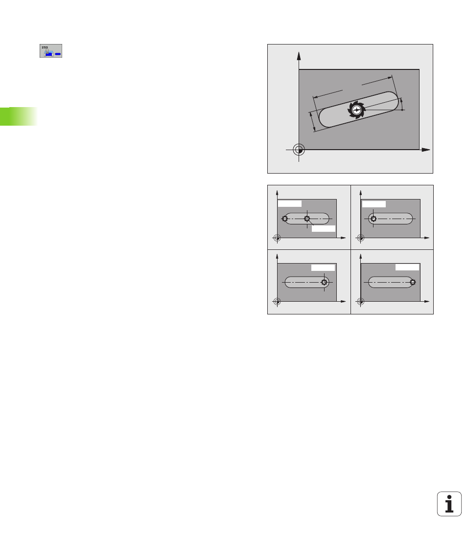
Slot length Q218 (value parallel to the reference axis
of the working plane): Enter the length of the slot.
Input range 0 to 99999.9999
U
Slot width Q219 (value parallel to the secondary axis
of the working plane): Enter the slot width. If you
enter a slot width that equals the tool diameter, the
TNC will carry out the roughing process only (slot
milling). Maximum slot width for roughing: Twice the
tool diameter. Input range 0 to 99999.9999
U
Finishing allowance for side Q368 (incremental):
Finishing allowance in the working plane.
U
Angle of rotation Q374 (absolute): Angle by which
the entire slot is rotated. The center of rotation is the
position at which the tool is located when the cycle is
called. Input range -360.000 to 360.000
U
Slot position (0/1/2/3/4) Q367: Position of the slot
in reference to the position of the tool when the cycle
is called:
0: Tool position = Center of slot
1: Tool position = Left end of slot
2: Tool position = Center of left slot circle
3: Tool position = Center of right slot circle
4: Tool position = Right end of slot
U
Feed rate for milling Q207: Traversing speed of the
tool during milling in mm/min. Input range: 0 to
99999.999; alternatively FAUTO, FU, FZ
U
Climb or up-cut Q351: Type of milling operation with
M3:
+1 = climb milling
–1 = up-cut milling
X
Y
Q21
9
Q218
Q374
X
Y
X
Y
X
Y
X
Y
Q367=0
Q367=1
Q367=2
Q367=3
Q367=4