Cycle parameters – HEIDENHAIN TNC 620 (340 56x-02) Cycle programming User Manual
Page 399
HEIDENHAIN TNC 620
399
16.1
1
MEA
S
URE COORDINA
TE (Cy
c
le
427
, DIN/ISO: G427)
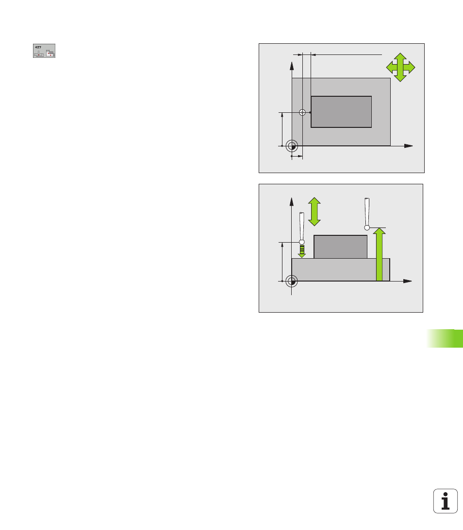
Cycle parameters
U
1st meas. point 1st axis Q263 (absolute): Coordinate
of the first touch point in the reference axis of the
working plane. Input range -99999.9999 to
99999.9999
U
1st meas. point 2nd axis Q264 (absolute):
Coordinate of the first touch point in the minor axis of
the working plane. Input range -99999.9999 to
99999.9999
U
Measuring height in the touch probe axis Q261
(absolute): Coordinate of the ball tip center (= touch
point) in the touch probe axis in which the
measurement is to be made. Input range
-99999.9999 to 99999.9999
U
Setup clearance Q320 (incremental): Additional
distance between measuring point and ball tip. Q320
is added to SET_UP (touch probe table). Input range
0 to 99999.9999
U
Measuring axis (1..3: 1=reference axis) Q272: Axis
in which the measurement is to be made:
1:Reference axis = measuring axis
2:Minor axis = measuring axis
3: Touch probe axis = measuring axis
U
Traverse direction 1 Q267: Direction in which the
probe is to approach the workpiece:
-1: Negative traverse direction
+1:Positive traverse direction
U
Clearance height Q260 (absolute): Coordinate in the
touch probe axis at which no collision between touch
probe and workpiece (fixtures) can occur. Input range
-99999.9999 to 99999.9999
X
Y
Q264
Q263
+
+
Q267
Q272=2
Q272=1
SET_UP(TCHPROBE.TP)
+Q320
X
Z
Q260
Q261
+
Q272=1
Q272=3
Q267