HEIDENHAIN TNC 620 (340 56x-02) Cycle programming User Manual
Page 135
HEIDENHAIN TNC 620
135
5.3 CIR
C
ULAR POCKET (Cy
c
le 252, DIN/ISO: G252, A
d
v
a
nced Pr
ogr
a
mming
F
e
at
ur
es Sof
tw
a
re
Option)
U
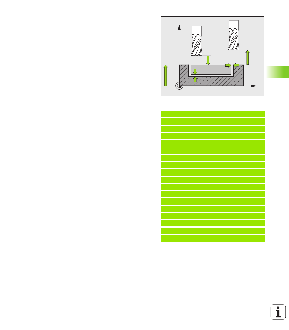
Setup clearance
Q200 (incremental): Distance
between tool tip and workpiece surface. Input range
0 to 99999.9999
U
Workpiece surface coordinate
Q203 (absolute):
Absolute coordinate of the workpiece surface. Input
range -99999.9999 to 99999.9999
U
2nd setup clearance
Q204 (incremental): Coordinate
in the spindle axis at which no collision between tool
and workpiece (fixtures) can occur. Input range 0 to
99999.9999
U
Path overlap factor
Q370: Q370 x tool radius =
stepover factor k. Input range 0.1 to 1.9999.
U
Plunging strategy
Q366: Type of plunging strategy.
0 = vertical plunging. The TNC plunges
perpendicularly, regardless of the plunging angle
ANGLE
defined in the tool table.
1 = helical plunging. In the tool table, the plunging
angle ANGLE for the active tool must be defined as
not equal to 0. The TNC will otherwise display an
error message.
U
Feed rate for finishing
Q385: Traversing speed of
the tool during side and floor finishing in mm/min.
Input range: 0 to 99999.999; alternatively FAUTO, FU,
FZ
Example: NC blocks
8 CYCL DEF 252 CIRCULAR POCKET
Q215=0
;MACHINING OPERATION
Q223=60
;CIRCLE DIAMETER
Q368=0.2
;ALLOWANCE FOR SIDE
Q207=500
;FEED RATE FOR MILLING
Q351=+1
;CLIMB OR UP-CUT
Q201=-20
;DEPTH
Q202=5
;PLUNGING DEPTH
Q369=0.1
;ALLOWANCE FOR FLOOR
Q206=150
;FEED RATE FOR PLUNGING
Q338=5
;INFEED FOR FINISHING
Q200=2
;SETUP CLEARANCE
Q203=+0
;SURFACE COORDINATE
Q204=50
;2ND SETUP CLEARANCE
Q370=1
;TOOL PATH OVERLAP
Q366=1
;PLUNGE
Q385=500
;FEED RATE FOR FINISHING
9 L X+50 Y+50 R0 FMAX M3 M99
X
Z
Q200
Q20
Q20
Q36
Q36