Cycle parameters – HEIDENHAIN TNC 620 (340 56x-02) Cycle programming User Manual
Page 294
294
Touch Probe Cycles: Automatic Measurement of Workpiece Misalignment
14.3 BA
SIC R
O
T
A
TION fr
om T
w
o Holes (Cy
c
le 40
1, DIN/ISO: G40
1
)
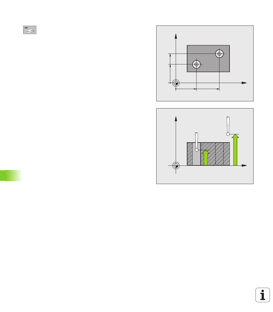
Cycle parameters
U
1st hole: Center in 1st axis Q268 (absolute): Center
of the first hole in the reference axis of the working
plane. Input range -99999.9999 to 99999.9999
U
1st hole: Center in 2nd axis Q269 (absolute): Center
of the first hole in the minor axis of the working plane.
Input range -99999.9999 to 99999.9999
U
2nd hole: Center in 1st axis Q270 (absolute): Center
of the second hole in the reference axis of the
working plane. Input range -99999.9999 to
99999.9999
U
2nd hole: Center in 2nd axis Q271 (absolute): Center
of the second hole in the minor axis of the working
plane. Input range -99999.9999 to 99999.9999
U
Measuring height in the touch probe axis Q261
(absolute): Coordinate of the ball tip center (= touch
point) in the touch probe axis in which the
measurement is to be made. Input range
-99999.9999 to 99999.9999
U
Clearance height Q260 (absolute): Coordinate in the
touch probe axis at which no collision between touch
probe and workpiece (fixtures) can occur. Input range
-99999.9999 to 99999.9999
U
Default setting for basic rotation Q307 (absolute): If
the misalignment is to be measured against a straight
line other than the reference axis, enter the angle of
this reference line. The TNC will then calculate the
difference between the value measured and the
angle of the reference line for the basic rotation. Input
range -360.000 to 360.000
X
Y
Q271
Q269
Q268
Q270
X
Z
Q261
Q260