2 before you start working with touch probe cycles – HEIDENHAIN TNC 620 (340 56x-02) Cycle programming User Manual
Page 281
HEIDENHAIN TNC 620
281
13.2 Bef
o
re
Y
ou Star
t W
o
rk
ing with T
ouc
h Pr
obe Cy
cles
13.2 Before You Start Working with
Touch Probe Cycles
To make it possible to cover the widest possible range of applications,
machine parameters enable you to determine the behavior common
to all touch probe cycles.
Maximum traverse to touch point: DIST in touch
probe table
If the stylus is not deflected within the path defined in DIST, the TNC
outputs an error message.
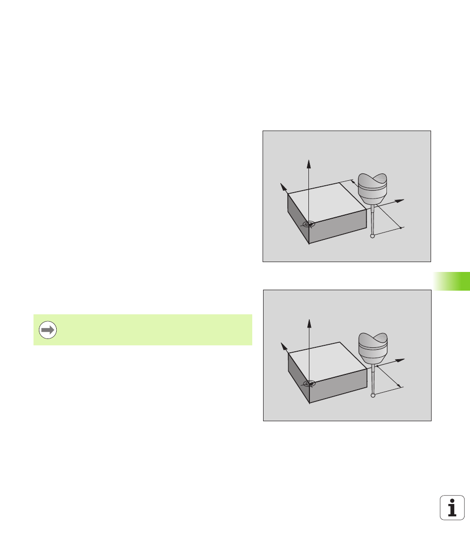
Setup clearance to touch point: SET_UP in touch
probe table
In SET_UP you define how far from the defined (or calculated) touch
point the TNC is to pre-position the touch probe. The smaller the value
you enter, the more exactly must you define the touch point position.
In many touch probe cycles you can also define a setup clearance that
is added to SET_UP.
Orient the infrared touch probe to the
programmed probe direction: TRACK in touch
probe table
To increase measuring accuracy, you can use TRACK = ON to have an
infrared touch probe oriented in the programmed probe direction
before every probe process. In this way the stylus is always deflected
in the same direction.
Y
X
Z
DIST
Y
X
Z
SET_UP
If you change TRACK = ON, you must recalibrate the touch
probe.