12 plc input/output unit pl 410 b/ pl 405 b – HEIDENHAIN TNC 370D User Manual
Page 30
July 02
Mounting and Electrical Installation
TNC 370 D
3–27
3.7.12 PLC input/output unit PL 410 B/ PL 405 B
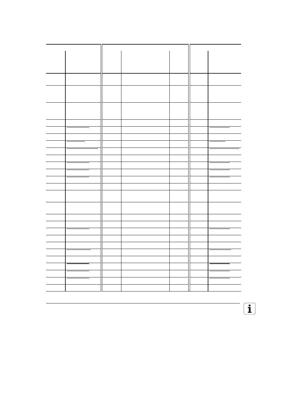
Up to two PL 410 B and one PL 405 B can be connected to the LE 370 D.
X47 PL 410 B/PL 405 B input/output unit on the LE
Logic unit
Connecting cable Id. Nr. 289 111 ..
1st PL 410 B
X47 D-sub
terminal
(male)
25-pin
Assignment D-sub
connector
(female)
25-pin
D-sub
connector
(male)
25-pin
X1 D-sub
terminal
(female)
25-pin
Assignment
1
0 V
1
Brown, Yellow, Pink, Red,
Violet
1 1
0
V
2
0 V
2
Red/Blue, Brown/Green,
Yellow/Brown, Gray/Brown,
Pink/Brown
2 2
0
V
3
0 V
3
Brown/Blue, Brown/Red,
Brown /Black, Yellow/Gray,
Yellow/Pink
3 3
0
V
4
Do not use
4
Gray/Green
4
4
Serial IN 2
5
Address 6
5 White/Green
5 5 Address 6
6 INTERRUPT 6
Pink/Green
6 6
INTERRUPT
7
RESET
7 Green/Blue
7 7 RESET
8
WRITE EXTERNAL
8 White/Blue
8 8 WRITE EXTERNAL
9
WRITE EXTERNAL
9
White/Red
9
9
WRITE EXTERNAL
10
Address 5
10 Gray/Pink
10 10 Address 5
11
Address 3
11 Blue
11 11 Address 3
12
Address 1
12 Green
12 12 Address 1
13
Do not use 13
13
13
Do not use
14
PCB identifier 4
14
Yellow/Blue, Pink/Blue,
Yellow/Black
14
14
+ 12 V
15
PCB identifier 3
15
Yellow/Red, Gray/Red,
Pink/Red
15
15
+ 12 V
16
Do not use
16
Gray/Blue
16
16
PCB identifier 2
17
Do not use
17
Green/Black
17
17
PCB identifier 1
18
Address 7
18 White/Yellow
18 18 Address 7
19
Serial IN 1
19
White/Black
19
19
Serial IN 1
20
EMERGENCY STOP
20
Green/Red
20
20
EMERGENCY STOP
21
Serial OUT
21 White/Gray
21 21 Serial OUT
22
Serial OUT
22
White/Pink
22
22
Serial OUT
23
Address 4
23 Black
23 23 Address 4
24
Address 2
24 Gray
24 24 Address 2
25
Address 0
25 White
25 25 Address 0
Housing External
shield
Housing
External
shield Housing
Housing
External
shield