Removing/replacing terminating resistors, Removing/replacing terminating resistors -32, Installation – Grass Valley Performer SD User Manual
Page 64
2-32
Section 2 —
Installation
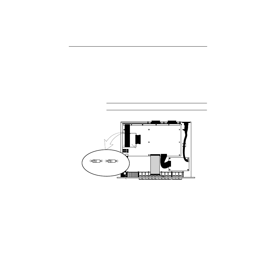
Removing/Replacing Terminating Resistors
When using your unit with more than one other device, you must
decide where your unit is to reside on the control bus. Depending
on its location on the bus, you may need to remove resistor R400.
■
If your unit will reside at the end of the bus, leave R400 in
place
■
If your unit will reside mid-bus, remove R400
■
R401 should not be installed in either case
NOTE:
The silkscreen text on board may be incorrect.
AC Line Cord
Receptacle
Bit-Rate
Mode
Select
Switch
AES/EBU IN/OUT 2
Connector
AES/EBU IN/OUT 1
Connector
optional
Tally Board
(066921-10)
40-pin ribbon cable
(054661-00)
26-pin ribbon cable
(052781)
40-pin ribbon cable
(054661-01)
Power Supply
(PE1298-00)
OPEN
1
2
3
4
5
6
7
8
OPEN
1
2
3
4
5
6
7
8
OPEN
12
34
5
6
7
8
S1
NOTE: If Tally Relay Board
or Looping option is installed,
ribbon cables may have to be
moved to see resistors.
R401
Remove
R400
Remove if not
at end of bus
S2
S3