Grass Valley Maestro Master Control v.1.7 User Manual
Page 164

160
Maestro Channel Branding User Guide
Section 5 — The Maestro Configuration Editor
Maestro Configuration
The GPIO Definition table is used to configure the GPIO ports on the rear
panel of the Maestro. The table is located in the Input/Output Sets group
of the Maestro Configurator. When the GPIO Definition table is first
opened, the editor will open a set panel. Create a name for the GPIO table,
select an Input Set (only required for Source Tally), then select “New.” (The
table is assigned to a Maestro channel using the Channel Setup table.)
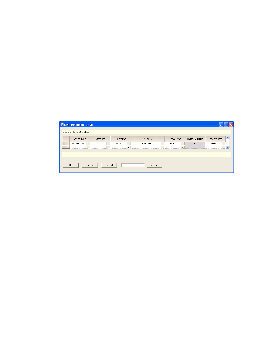
External Device Control of Maestro (Action: Transition)
In this application, an external device can send a Transition (Take)
command to the Maestro. See
.
Figure 123. GPIO Definition table for “Transition” Trigger to Maestro
Device Type
Select the MaestroGPI option from the drop-down list for this application.
Identifier
The numbers in this column refer to the 16 ports on the GPIO connector.
Any port from 1 to 16 can be selected in any order. The 16 available ports
can be assigned only once, either as a GPI or a GPO depending upon its
intended usage.
Sub System
Select the Action option from the drop-down list.
Note
The other available sub system selection with the MaestroGPI device types is
“EAS.” Although this implies it can only be used with Emergency Alert
System implementations, it is generically used to externally trigger the inser-
tion of keyers and audio overs.
Purpose
Select the Transition option from the drop-down list.
Note
Transition is the only choice when MaestroGPI is the device type.
