Grass Valley Maestro Master Control v.1.7 User Manual
Page 117
Maestro Channel Branding User Guide
113
1st Step: Connections
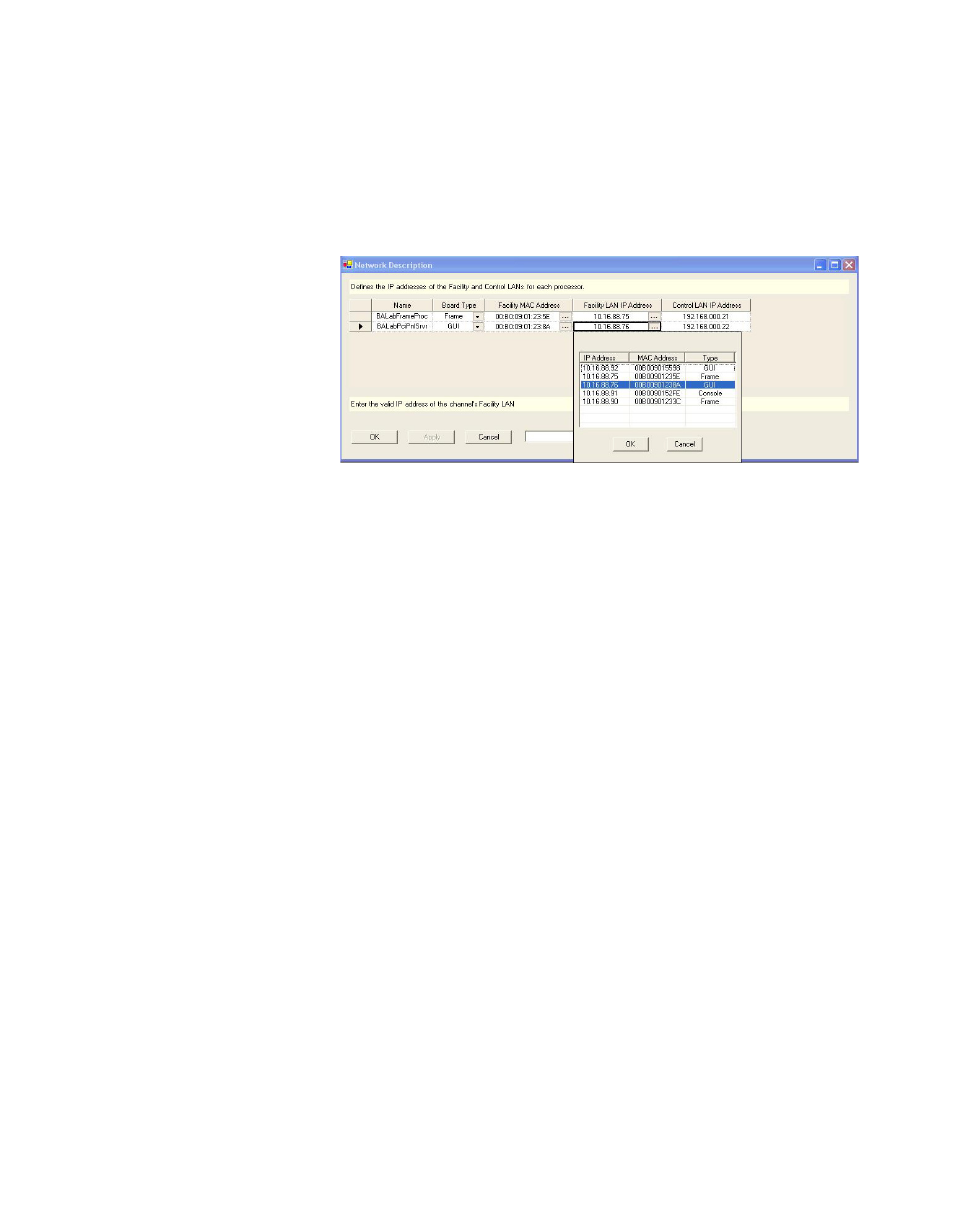
Facility MAC Address
Click on the “
...”
button and select the MAC address of the component
being named.
shows an example of the window that appears
after clicking the “
...
” button.
Figure 88. Board Discovery in Network Description Table
The 12-character MAC (physical hardware) address is shown on a label
attached to each component.
Note
If a component does not appear in the drop-down menu, it may be that the
facility LAN address of the Configuration PC was not set properly, the device
is not powered on, or the Configuration PC is not present on the Facility LAN.
Facility LAN IP Address
This field will be filled in automatically when the facility MAC Address is
selected.
Control LAN IP Address
Enter a corresponding IP address for use on the control LAN.
Note
If a control LAN address is entered for the GUI, that address must also be
entered on the GUI Application Settings menu as the “Panel Server IP.”
Repeat the above steps for each Maestro component.
When finished, Click the
Apply
button, and then the
OK
button to save the
information.
Note
After all the configuration tables are edited and saved you must “compile” the
set before it can be downloaded using the Deployment Control Center. This
process is described in Compile Current Configuration