Rs-422 connection diagram – Grass Valley Kaleido-Modular-X v.7.70 User Manual
Page 51
47
Kaleido-Modular-X
Quick Start Guide
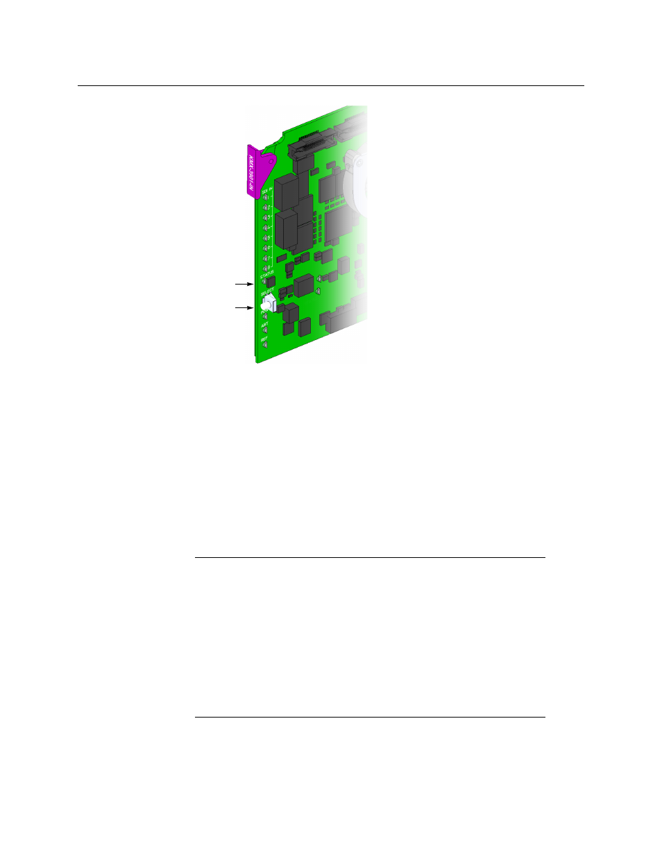
The Status LED on the selected card flashes orange, and the associated control menu
appears on the display of the Densité frame’s local control panel.
2 On the local control panel, press the [–] button.
The version of the Kaleido-X Software that is running on the card (e.g. “7.10-
build.5201”) appears on the display.
3 Press the Select button on the front edge of the input card to exit the control menu.
RS-422 Connection Diagram
Output cards paired with a double rear connector panel support one RS-422 port over an
RJ-45 connector. This port allows the Kaleido-Modular-X to connect to external serial
devices such as a router, production switcher, or router controller.
The pinout for the RS-422 signals on the RJ-45 connectors, and the wiring diagrams for the
appropriate adapters, are shown here:
Select button
Status LED
Notes
• The single rear connector panel KMX-3901-OUT-D-3+SRP does not have a
serial port. To support a serial device, your Kaleido-Modular-X system must
have at least one output card with a double rear connector panel
(KMX-3901-OUT-D-3DRP).
• The RS-422 ports each have an RJ-45 connector in order to preserve space
on a busy panel. The RS-422 interface specifies a DE-9 connector, so if you
are using this interface, you will require a DE-9-to-RJ-45 adapter. Grass
Valley supplies two adapter models, correctly wired for this application: a
straight adapter (part no. 1737-3000-102), and a crossover adapter (part
no. 1792-3700-100).
- Kaleido-Modular-X Jun 11 2014 Kaleido-MX 4K (1RU) Quick Start v.7.80 Kaleido-MX 4K (3RU) Quick Start v.7.80 Kaleido-MX (1RU) Quick Start v.7.80 Kaleido-MX (1RU) Quick Start v.7.70 Kaleido-MX (1RU) Quick Start Jul 16 2014 Kaleido-MX (3RU) Quick Start v.7.80 Kaleido-MX (1RU) Quick Start Dec 17 2014 Kaleido-MX (3RU) Quick Start v.7.70 Kaleido-MX (3RU) Quick Start Jul 16 2014 Kaleido-MX (3RU) Quick Start Dec 17 2014