Grass Valley Kaleido-Modular-X v.7.70 User Manual
Page 12
8
Setting Up Your Kaleido-Modular-X System
Physical Setup
3 Remove the blank rear panels that cover the slots where you wish to install your cards,
by releasing their captive screws.
4 Position the new rear panels, and secure them in place with the captive screws at the
bottom (or on the right, in the case of a Densité 3+ FR1 frame).
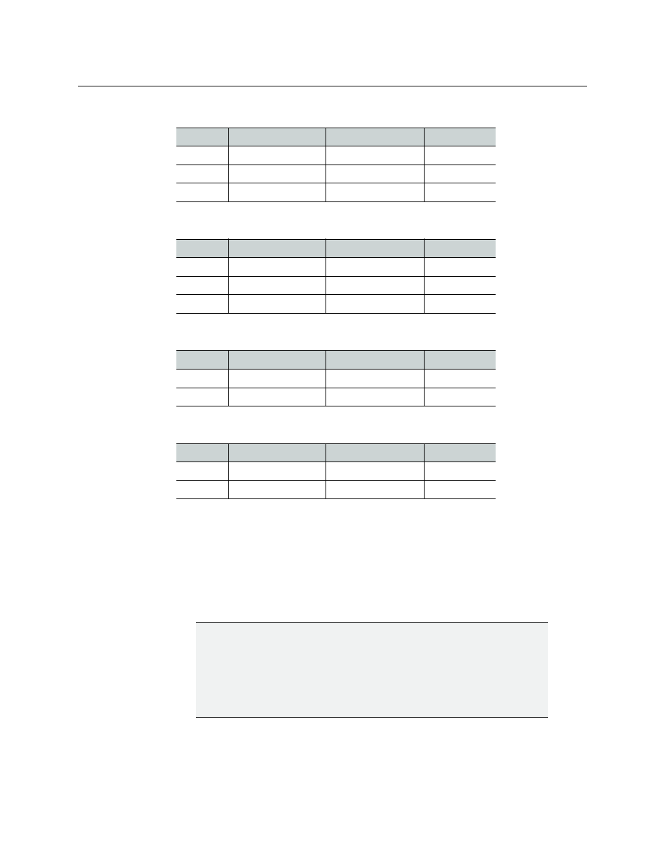
5 Slide each of your new input and output cards into the appropriate slot (refer to the
table matching your intended configuration, above, if needed), and push gently on the
handle to seat the connectors. Seating an input card requires more pressure.
6 Verify that each card is securely seated in its slot, and leave the frame door open so that
you can monitor all the card’s LEDs.
24 × 2
Card
Model
Rear panel covers...
Insert card at...
Output A
KMX-3901-OUT-D
Slots 2–3
Slot 2
Input A
KMX-3901-IN-16-D
Slots 4–7
Slot 6
Input B
KMX-3901-IN-8-D
Slots 8–10
Slot 9
16 × 4
Card
Model
Rear panel covers...
Insert card at...
Output B
KMX-3901-OUT-D
Slots 2–3
Slot 2
Output A
KMX-3901-OUT-D
Slots 4–5
Slot 4
Input A
KMX-3901-IN-16-Q
Slots 6–10
Slot 8
16 × 2, 16 × 1
Card
Model
Rear panel covers...
Insert card at...
Output A
KMX-3901-OUT-D
Slots 1–2
Slot 1
Input A
KMX-3901-IN-16-D
Slots 3–6
Slot 5
8 × 2, 8 × 1
Card
Model
Rear panel covers...
Insert card at...
Output A
KMX-3901-OUT-D
Slots 2–3
Slot 2
Input A
KMX-3901-IN-8-D
Slots 4–6
Slot 5
IMPORTANT
• If you need to replace or momentarily remove a rear panel, make sure to
first remove the corresponding card itself from its slot (see Replacing Cards,
in the Kaleido-Modular-X Hardware Description & Installation Manual).
• Removing more than one input card at a time from a Kaleido-Modular-X
system in operation is not supported.
- Kaleido-Modular-X Jun 11 2014 Kaleido-MX 4K (1RU) Quick Start v.7.80 Kaleido-MX 4K (3RU) Quick Start v.7.80 Kaleido-MX (1RU) Quick Start v.7.80 Kaleido-MX (1RU) Quick Start v.7.70 Kaleido-MX (1RU) Quick Start Jul 16 2014 Kaleido-MX (3RU) Quick Start v.7.80 Kaleido-MX (1RU) Quick Start Dec 17 2014 Kaleido-MX (3RU) Quick Start v.7.70 Kaleido-MX (3RU) Quick Start Jul 16 2014 Kaleido-MX (3RU) Quick Start Dec 17 2014