2 functions in the vfo mode, 1 vfo link function – Alinco DJ-X2000 User Manual
Page 62
61
3.2 Functions in the VFO mode
This section describes various functions available in the VFO mode.
3.2.1 VFO link function
This function is used to synchronously change two VFO frequencies, the
currently received frequency and another frequency.
1
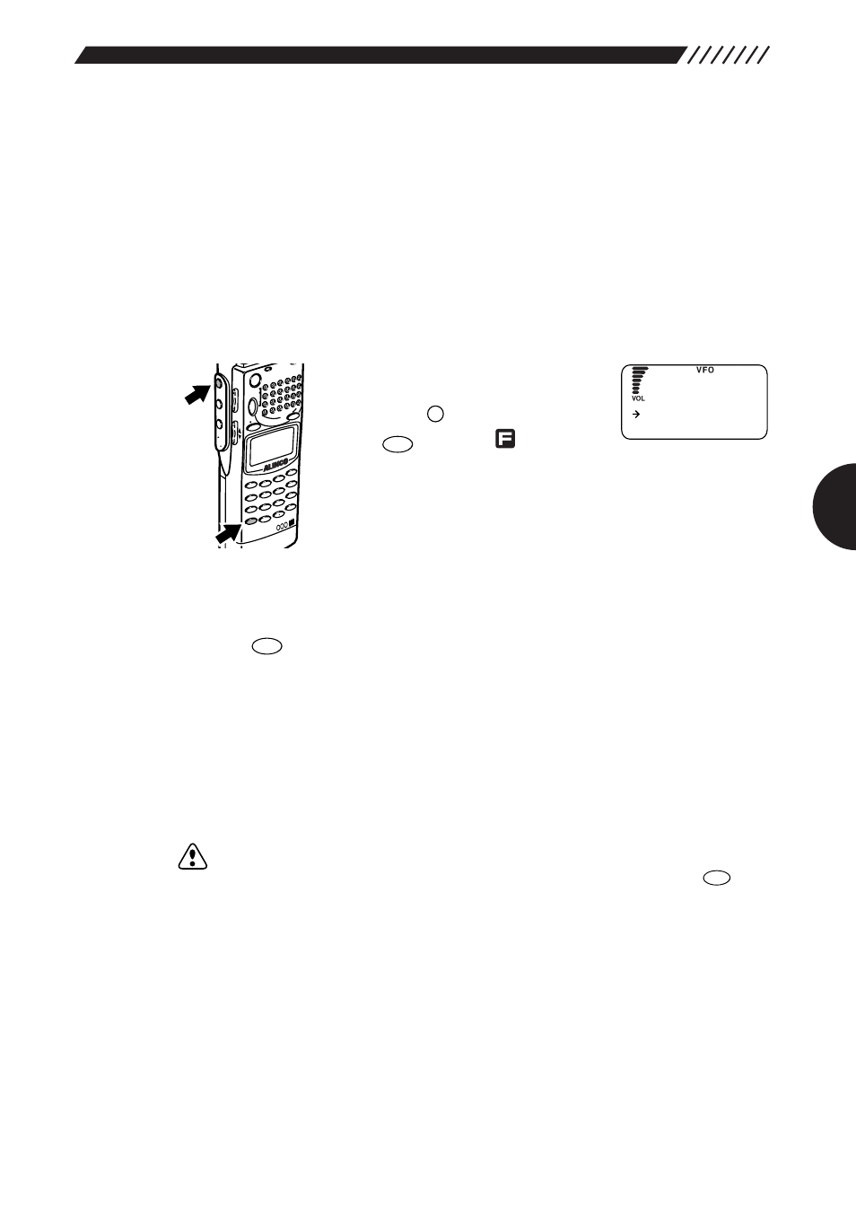
Call up the LINK SET screen.
Specify frequencies in bands A
and B of VFO.
Press the
key, and then press
the key
while
is
shown
on the display.
The LINK SET screen will appear.
2
Select a type of the VFO link function.
Point the arrow at the desired option using the dial or
UP/DOWN
key, and then
press the
key (the initial setting is
LINK OFF
).
AUTO LINK
The frequencies in bands A and B interlock and change
at the interval that was set using the auto link function.
USER LINK
Both bands A and B are displayed in capital letters and
the VFO link function becomes active. As the frequency
on the upper line of the display is changed, the one on
the lower line changes simultaneously.
LINK OFF
The VFO link function is canceled.
Note:
The frequency on the upper line may exceed 2149.999950 MHz (the upper
limit for the DJ-X2000) when it is changed. In this case, press the
key
toggle between bands A and B. The band shown on the upper line will be
switched to the lower line. The band shown on the lower line (exceeding
2149.9999 MHz) will be included in a range between 0.1 MHz and
2149.999 MHz and then switched to the upper line while maintaining the
difference between the two frequencies. The VFO link function is not
canceled.
A=B
VFO
ENT
TF
CLR
SKIP
F
MODE
AUTO
MW
INTELLIGENT
RECEIVER
DJ-X2
MIC
SCRT
PRIO
REC
CTCSS
F TUN
E
A-B S
M NAM
E
TF
SKIP
STEP
ATT
SET
POW
ER
RX/S
T
PMS
VFO
MR M
W
A B
SET
KL
3
6
9
8
0
5
2
1
4
CLR
ENT
MIC
SCN
RF C
HELP
7
MON
I
F
SRCH
LAMP
SQL VOL
D
OW
N UP
AU T O L I NK
US ER L I NK
L I NK SET