System failure, Alarms, System failure -2 alarms -2 – Verilink AS2000: The Basics (880-502981-001) Product Manual User Manual
Page 68
Monitoring and Troubleshooting
5-2
Verilink Access System 2000: The Basics
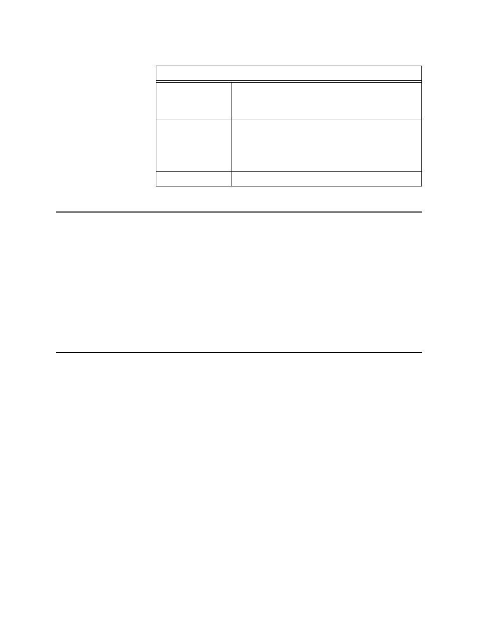
Table 5-2 Test Equipment
System Failure
System failure can be caused by many different problems. System
faults are not always attributed to component failure. Outside
influences such as circuit lines (T1) and application equipment
(customer-provided equipment) can cause degraded performance
and/or loss of service.
On initial system start-up, faults are traced to an errored system
configuration. Refer to the individual component documentation
for specific configuration requirements, and module fault
indications.
Alarms
Controller modules poll the various application modules for
alarms. If alarm reporting is enabled for the node and for the
application modules, the node controller card retrieves and sends
the alarm to the Craft interface, Node Manager, or an SNMP agent.
An alarm list is provided under the alarm displays of the various
options of the Craft interface, Node Manager, or SNMP.
Alarm conditions are defined as:
•
Critical (power supply failure)
•
Major
•
Minor
•
Warning
•
Informational
Test Equipment
Transmission Test
Set
Test set must send and measure various test patterns
(QRSS, etc.) in the framing and line coding formats
required by the circuit under test (T1, E1, DS3, ISDN,
etc.).
Bit Error Rate
Tester (BERT)
Test set must generate and measure data at the same
transmission rates and interfaces (RS-449, V.35, or EIA
530) used by the customer data equipment. If
handshaking control is used by the DSU ports, the
data test set must monitor and indicate handshaking
control signal status.
Digital Voltmeter
Used for measuring AC and DC voltages.