System power application and verification, System power application and verification -14, Applying multi-line shelf dc power -14 – Verilink AS2000: The Basics (880-502981-001) Product Manual User Manual
Page 60: Applying multi-line shelf dc power
Hardware Installation
4-14
Verilink Access System 2000: The Basics
•
If the STAT LED is amber, check the incoming clock signal rate
and format.
•
If the STAT LED is red, verify that the clock source is providing
an output to the TIU.
•
If the STAT LED flashes red, the TIU is receiving more than one
clock. Disconnect one of the incoming clock signals from the
CIM 2010.
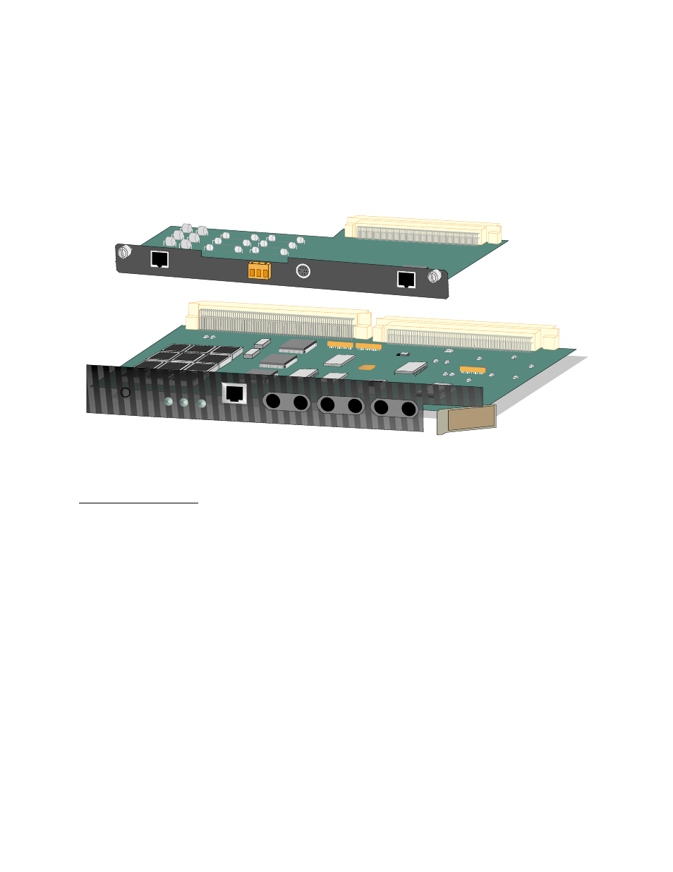
Figure 4-13 TIU 2850 LEDs and CIM 2010 Connectors
System Power
Application and
Verification
The following procedures apply to Multi-line and Dual-line shelf
power application and verification. Use a digital voltmeter to
measure the input and output voltages of each power supply.
Applying Multi-line
Shelf DC Power
To apply power to -48 VDC power supplies (PDC 2920), refer to
, and do the following:
1. Remove the protective cover on the rear of the shelf.
2. Insert a fuse for each power supply (A and B) into the
associated distribution panel.
3. Measure the voltage between pins 30 and 32 on Power Supply
A (J-15). The correct voltage is between -42V and -56V.
4. Measure between pins 30 and 32 on Power Supply B (J-14). The
correct voltage is between -42V and -56V.
5. Verify that the Power LED is lit green on the front panel of the
power supply.
CIM
2010
EQPT
Network
EXT TIMING
NO COM NC
ALARM
RELAY
STAT
EQPT
NET
T1 CLOCK
MON
EQPT
IN
TIU 2850