Setting the shelf address -18, Table 4-1 – Verilink AS2000: The Basics (880-502981-001) Product Manual User Manual
Page 64
Hardware Installation
4-18
Verilink Access System 2000: The Basics
Table 4-1
AS2000 Cable UsageACP Shelf Addressing and Extension
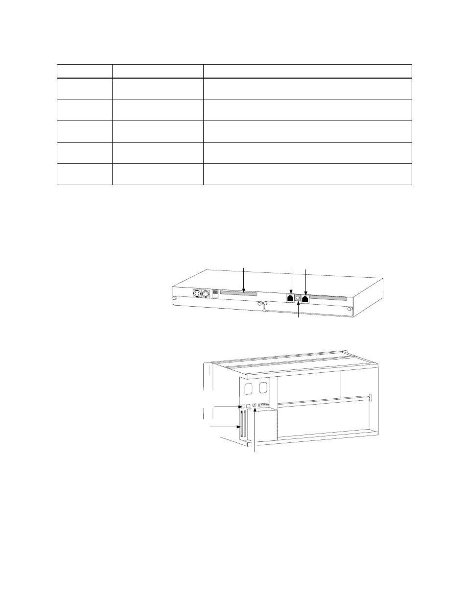
This section provides information to set the shelf address and
install the node controller bus expansion cables.
illustrates the shelf-address switch locations for a Multi-line and
Dual-line shelf.
Figure 4-16 Address Switches and Bus Expansion Ports
Setting the Shelf
Address
The shelf address is set with the shelf address switch (SW1),
located on the Multi-line and Dual-line shelf backplanes. To set the
address, do the following:
1. Using a small flat-blade screwdriver, set the shelf address on
shelf 1 by rotating the address switch to position 1.
Cable Number Cable Type
Usage
1
Controller bus expansion
cables
Extends the TABs-based network management path from
shelf to shelf. Uses RJ-11 connectors.
2
DSX-1 or CEPT-1 T1/E1
equipment cables
Used for bi-directional drop-and-insert applications for T1/E1
signal connections between a CSU and T1/E1 equipment.
3
Network interface cables
Connects a network port to a network service. Uses RJ-48C
or DB-15 connectors.
4
Network management
cables
Used to connect network management software to the
AS2000 node.
5
Craft interface cables
Used to connect an ASCII terminal to an NCC, SCC, NCM, or
ACP-based application module.
Data Bus
Expansion Port
Shelf Address Switch
Shelf Address Switch
Data Bus
Expansion Port
RJ-11 Controller
Bus Expansion Port
RJ-11 Controller
Bus Expansion Port