Data bus expansion, Connecting the rear connector modules, Ascii terminal connection – Verilink AS2000: The Basics (880-502981-001) Product Manual User Manual
Page 66
Hardware Installation
4-20
Verilink Access System 2000: The Basics
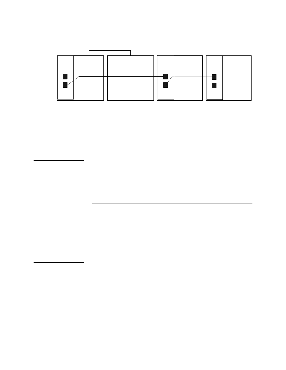
Figure 4-18 Daisy Chaining for NCM
The NCM in shelf 1 connects to shelf 3 (in this example) through
the EXT connector on the NCM and the PRI connector on the ACP
type card in shelf 3. Shelf 2 contains all TABS modules. It is
extended from Shelf 1 using the backplane RJ-11 connectors, as in
a legacy AS2000 system. Shelves 3 and 4 have DIDCSU application
modules which use the ACP bus.
Data Bus
Expansion
The data-bus expansion cable for an NCC- or SCC-based node is a
50-lead ribbon cable. This cable extends the three midplane data
buses (A, B, and C) from one shelf to the next. Plug the cable into
the data-bus expansion port from shelf one to the next shelf. Refer
to
for the location of the shelf data-bus expansion
ports.
NOTE: There is no data-bus expansion for NCM-based nodes.
Connecting the
Rear Connector
Modules
Connect the designated cables to the rear connector modules.
Make the network management connections to the supplied
Ethernet transceiver ports if using an NCM or SCC.
ASCII Terminal
Connection
Connect a Craft cable to the port labeled L
OCAL
on the front of the
controller module. Connect the other end of the Craft cable to your
PC or terminal. If using a PC, start a session in a terminal program.
1. Set your terminal parameters to:
•
19.2 kbit/s
•
8 data bits
•
No parity
•
One stop bit
•
No flow control
NCM
PRI
EXT
IAD
PRI
EXT
IAD
PRI
EXT
All TABS shelf
RJ-11 backplane cable extends TABS bus
Shelf 1 ACP
Shelf 3 ACP
Shelf 4 ACP
Shelf 2 TABS